1-70
Cisco ONS 15310-CL and Cisco ONS 15310-MA Troubleshooting Guide, R7.0
Chapter 1 General Troubleshooting
1.11.2 Faulty Fiber-Optic Connections
Warning
Class 1 laser product.
Statement 1008
Warning
Laser radiation presents an invisible hazard, so personnel should avoid exposure to the laser beam.
Personnel must be qualified in laser safety procedures and must use proper eye protection before
working on this equipment.
Statement 300
Verify Fiber-Optic Connections
Step 1 Ensure that a single-mode fiber connects to the ONS 15310-CL or ONS 15310-MA Small form-factor
Pluggable (SFP).
SM or SM Fiber should be printed on the fiber span cable. ONS 15310-CL and ONS 15310-MA ports
do not use multimode fiber.
Step 2 Ensure that the connector keys on the SC fiber connector are properly aligned and locked.
Step 3 Check that the single-mode fiber power level is within the specified range:
a. Remove the Rx end of the suspect fiber.
b. Connect the receive end of the suspect fiber to a fiber-optic power meter, such as a
GN Nettest LP-5000.
c. Determine the power level of fiber with the fiber-optic power meter.
d. Verify that the power meter is set to the appropriate wavelength for the optical port being tested
(either 1310 nm or 1550 nm).
e. Verify that the power level falls within the range specified for the card; refer to the
Cisco ONS 15310-CL and Cisco ONS 1310-MA Reference Manual for information.
Step 4 If the power level falls below the specified range:
a. Clean or replace the fiber patchcords. Clean the fiber according to site practice or, if none exists,
follow the procedure in the Cisco ONS 15310-CL and Cisco ONS 15310-MA Procedure Guide. If
possible, do this for the OC-N port you are working on and the far-end ONS 15310-CL or
ONS 15310-MA.
b. Clean the optical connectors on the port. Clean the connectors according to site practice or, if none
exists, follow the procedure in the Cisco ONS 15310-CL and Cisco ONS 15310-MA Procedure
Guide. If possible, do this for the card you are working on and the far-end node.
c. If the power level still falls below the specified range with the replacement fibers and replacement
card, check for one of these three factors that attenuate the power level and affect link loss (LL):
• Excessive fiber distance—Single-mode fiber attenuates at approximately 0.5 dB/km.
• Excessive number or fiber connectors—Connectors take approximately 0.5 dB each.
• Excessive number of fiber splices—Splices take approximately 0.5 dB each.
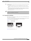
Note These are typical attenuation values. Refer to the specific product documentation for the
actual values or use an optical time domain reflectometer (OTDR) to establish precise link
loss and budget requirements.


