


7-13
Cisco Intrusion Prevention System Appliance and Module Installation Guide for IPS 7.1
OL-24002-01
Chapter 7 Installing the IPS 4510 and IPS 4520
Installing the IPS 4510 and IPS 4520
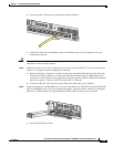
b. Connect one RJ-45 connector to the Management 0/0 interface.
c. Connect the other end of the Ethernet cable to the Ethernet port on your computer or to your
management network.
Caution Management and console ports are privileged administrative ports. Connecting them to an untrusted
network can create security concerns.
Step 3 (Optional) Connect to the sensor console port if you want to use the IPS CLI. Use the console port to
connect to a computer to enter configuration commands.
a. Before connecting a computer or terminal to any ports, determine the baud rate of the serial port.
The baud rate of the computer or terminal must match the default baud rate (9600 baud) of the
console port of the adaptive security appliance. Set up the terminal as follows: 9600 baud (default), 8
data bits, no parity, 1 stop bits, and Flow Control (FC) = Hardware.
b. Connect the RJ-45 to the console port and connect the other end to your computer.
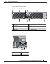
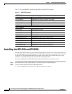
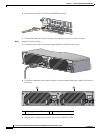
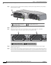
Step 4 (Optional) Connect to the SFP/SFP+ port if you are using fiber ports. The IPS 4510 and the IPS 4520
have four SFP/SFP+ ports. If you are using the fiber ports, you need an SFP+ module for 10-Gigabit
Ethernet or an SFP module for 1-Gigabit Ethernet (SFP or SFP+ modules are not included).
a. Install the SFP/SFP+ module.
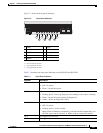
USB
0
101234567
MGMT
0
1
253908
9
8
SFP/SFP+
7
6
253906