


7-15
Cisco Intrusion Prevention System Appliance and Module Installation Guide for IPS 7.1
OL-24002-01
Chapter 7 Installing the IPS 4510 and IPS 4520
Removing and Installing the Core IPS SSP
Step 6 Power on the sensor.
Caution If the appliance is subjected to environmental overheating, it shuts down and you must manually power
cycle it to turn it on again.
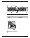
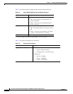
Step 7 Check the PWR indicator on the front panel of the sensor to verify power socket connectivity. It should
be green. To verify power supply operation, check the PS0 and PS1 indicators on the front panel. They
should be green. On the back panel of the sensor, make sure the IN OK and the FAN OK indicators are
green and the OUT FAIL indicator is off.
For More Information
For a list of the supported SFP/SFP+ modules, see Supported SFP/SFP+ Modules, page 7-11.
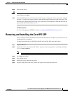
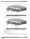
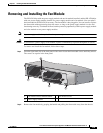
Removing and Installing the Core IPS SSP
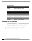
You can uninstall the core IPS SSP in the IPS 4510 and IPS 4520, for example, if you need to move it to
a different chassis or replace it.
To remove and install the core IPS SSP in the IPS 4510 and IPS 4520, follow these steps:
Step 1 Log in to the CLI.
Step 2 Prepare the sensor to be powered off. Wait for the power down message before continuing with Step 3.
sensor# reset powerdown
Note You can also power off the sensor using the IDM or the IME.
Step 3 Press Enter to confirm.
Step 4 Power off the sensor.
Step 5 Remove the power cable from the sensor.
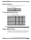
Step 6 From the front panel of the sensor, loosen the captive screws from the bottom slot.