


7-31
Cisco Intrusion Prevention System Appliance and Module Installation Guide for IPS 7.1
OL-24002-01
Chapter 7 Installing the IPS 4510 and IPS 4520
Rack-Mounting the Chassis Using the Fixed Rack Mount
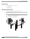
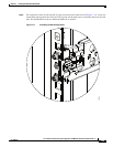
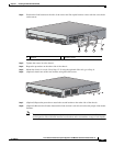
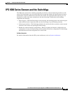
Step 2 Position the front bracket on the side of the sensor and line up the bracket screws with the screw holes
on the sensor.
Step 3 Tighten the screws in to the chassis.
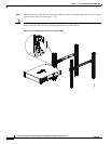
Step 4 Repeat the procedure on the other side of the chassis.
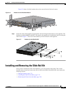
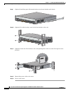
Step 5 Mount the chassis in a rack. Go to Step 12. If using the optional slide rails, go to Step 6.
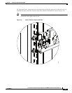
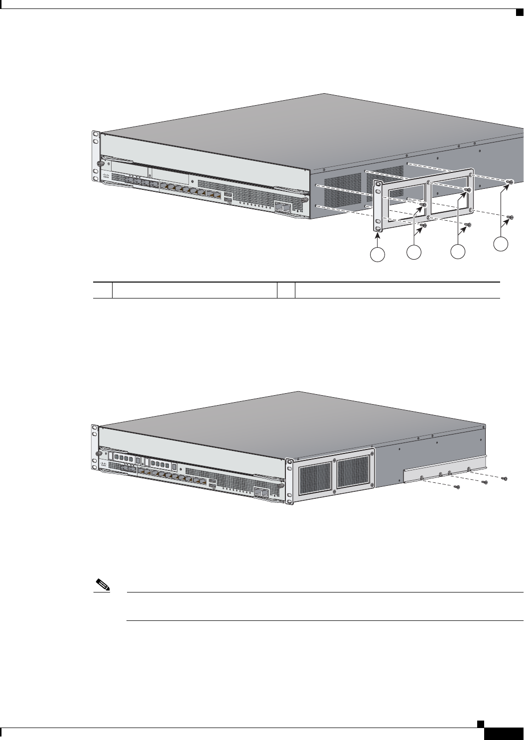
Step 6 (Optional) Attach one of the rear brackets using three M4 screws.
Step 7 (Optional) Repeat the procedure to attach the second bracket to the other side of the chassis.
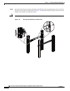
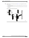
Step 8 (Optional) Measure the distance between the front and rear rack rails and select the proper slide-mount
brackets.
Note The slide-mount brackets let you install the rear of the chassis to the rear rack rails. The brackets
are designed to slide within the installed rear brackets and accommodate a range of rack depths.
1 Bracket 2 Bracket screws
1
2
2
2
PWR
BOOT
ALARM
ACT
VPN
PS1
HDD1
PS0
HDD0
USB
RESET
0
SFP1
SFP0
1
012
34567
MGMT
0
1
AUX CONSOLE
Cisco IPS 4510
PWR
BOOT
ALARM
ACT
VPN
PS1
HDD1
PS0
HDD0
USB
RESET
0
SFP3
SFP2
SFP1
SFP0
10
1
2
345
MGMT
0
1
AUX
CONSOLE
331821
PWR
BOOT
ALARM
ACT
VPN
PS1
HDD1
PS0
HDD0
USB
RESET
0
SFP1
SFP0
101234567
MGMT
0
1
AUX
CONSOLE
Cisco IPS 4510