


7-8
Cisco Intrusion Prevention System Appliance and Module Installation Guide for IPS 7.1
OL-24002-01
Chapter 7 Installing the IPS 4510 and IPS 4520
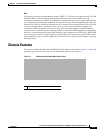
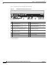
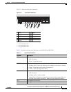
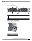
Chassis Features
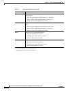
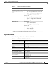
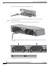
Table 7-2 describes the power supply module and fan module indicators.
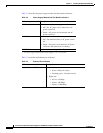
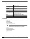
Table 7-3 describes the Ethernet port indicators.
Table 7-2 Power Supply Module and Fan Module Indicators
Indicator Description
IN OK Indicates status of power supply module:
• Off—No AC power cord connected or AC
power switch off.
• Green—AC power cord connected and AC
power switch on.
FAN OK Indicates status of fan module
• Off—Fan module failure or AC power switch
off.
• Green—AC power cord connected, AC power
switch on, and internal fan is running.
OUT FAIL
• Red—Output voltage failure
1
1. The power supply module has three output voltages—3.3V, 12V, and 50V.
Table 7-3 Ethernet Port Indicators
Indicator Description
Gigabit Ethernet (RJ45)
• Left side:
–
Green—Physical activity
–
Flashing green—Network activity
• Right side:
–
Not lit—10 Mbps
–
Green—100 Mbps
–
Amber—1000 Mbps