


7-6
Cisco Intrusion Prevention System Appliance and Module Installation Guide for IPS 7.1
OL-24002-01
Chapter 7 Installing the IPS 4510 and IPS 4520
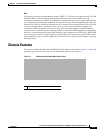
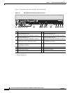
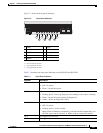
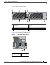
Chassis Features
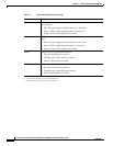
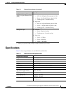
PS1 Indicates the state of the power supply module installed on the right when facing
the back panel:
• Off—No power supply module present or no AC input.
• Green—Power supply module present, on, and good.
• Amber—Power or fan module off or failed.
PS0 Indicates the state of the power module installed on the left when facing the back
panel:
• Off—No power supply module present or no AC input.
• Green—Power supply module present, on, and good.
• Amber—Power or fan module off or failed.
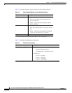
HDD1
2
Indicates activity on the hard disk drive:
• Off—No hard disk drive present.
• Flashing green—Hard disk drive activity.
• Amber—Hard disk drive failure.
HDD2
3
Indicates activity on the hard disk drive:
• Off—No hard disk drive present.
• Flashing green—Hard disk drive activity.
• Amber—Hard disk drive failure.
1. OIR is not available at this time.
2. The hard disk drive bays are reserved for future use.
3. The hard disk drive bays are reserved for future use.
Table 7-1 Front Panel Indicators (continued)
Indicator Description