


7-20
Cisco Intrusion Prevention System Appliance and Module Installation Guide for IPS 7.1
OL-24002-01
Chapter 7 Installing the IPS 4510 and IPS 4520
Installing the Slide Rail Kit Hardware
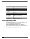
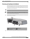
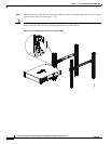
Step 3 Install the new fan module by aligning it with the fan module bay and pushing it into place until it is
seated.
Step 4 Tighten the captive screws.
Step 5 Verify that the fan indicator on the lower right-hand of the back panel is green.
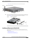
Installing the Slide Rail Kit Hardware
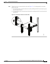
Before installing the appliance in the slide rail kit, you must install the slide rail kit hardware.
To install the slide rail kit hardware on the IPS 4510 and IPS 4520, follow these steps:
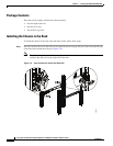
Step 1 Power off the appliance.
Step 2 Remove the power cable from the appliance.
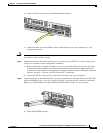
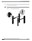
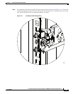
Step 3 If your appliance has the fixed cable management brackets, do the following:
a. Remove the cable management brackets from the front sides of the appliance.
b. Remove the appliance from the rack.
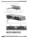
c. Remove the front brackets, left and right side brackets, and left and right rear brackets from the
appliance.
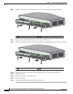
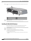
1 Fan module and fan handle 2 Fan module screw
3 Power supply module
Cisco ASA 1200W AC
100-240V
15.0/8.0.A
56/60Hz
IN
OK
FAN
OK
OUT
FAIL
253910
Cisco-ASA-FAN
Cisco-ASA-FAN
2
1
2
3