


7-21
Cisco Intrusion Prevention System Appliance and Module Installation Guide for IPS 7.1
OL-24002-01
Chapter 7 Installing the IPS 4510 and IPS 4520
Installing and Removing the Slide Rail Kit
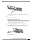
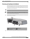
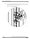
Figure 7-6 shows all of the brackets that can be removed for the fixed rack mount.
Figure 7-6 Brackets for the Fixed Rack Mount
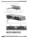
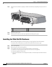
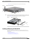
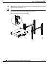
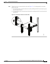
Step 4 Attach the slide rail kit hardware (front brackets and left and right side brackets) to the appliance. The
brackets are labelled RIGHT and LEFT. This prepares the appliance for installation in the rack using the
slide rail kit. Figure 7-7 shows all of the brackets you need to install on the appliance.
Figure 7-7 Brackets for the Slide Rail Kit
Installing and Removing the Slide Rail Kit
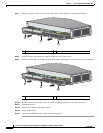
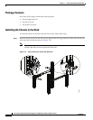
After you have installed the slide rail kit hardware, you can install the slide rail kit. This section
describes how to install and remove the slide rail kit for the IPS 4510 and IPS 4520, and contains the
following sections:
• Package Contents, page 7-22
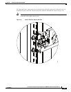
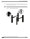
• Installing the Chassis in the Rack, page 7-22
• Removing the Chassis from the Rack, page 7-28
344202
PWR
BOOT
ALARM
ACT
VPN
PS1
HDD1
PS0
HDD0
USB
RESET
0
SFP1
SFP0
1
01
234567
MGMT
0
1
AUX CONS OLE
PWR
BOOT
ALARM
ACT
VPN
PS1
HDD1
PS0
HDD0
USB
RESET
0
SFP1
SFP0
101
234567
MGMT
0
1
AUX CONSOLE
333331