


7-16
Cisco Intrusion Prevention System Appliance and Module Installation Guide for IPS 7.1
OL-24002-01
Chapter 7 Installing the IPS 4510 and IPS 4520
Removing and Installing the Core IPS SSP
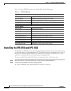
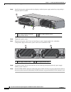
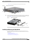
Step 7 Grasp the ejection levers at the left and right bottom of the designated slot and pull them out.
Step 8 Grasp the sides of the module and pull it all the way out of the chassis.
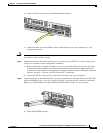
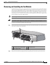
Step 9 Install the new module by lining it up with the module slot making sure the ejection levers are extended.
Step 10 Slide the module into the slot until it is seated and push the ejection levers back into place.
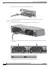
Step 11 Tighten the screws.
Step 12 Reconnect the power cable to the sensor.
Step 13 Power on the sensor.
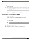
Step 14 Verify that the PWR indicator on the front panel is green.
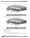
1 Module 2 Ejection levers
1 Module 2 Ejection levers
PWR
BOOT
ALARM
ACT
VPN
PS1
HDD1
PS0
HDD0
USB
RESET
0
SFP1
SFP0
10
1
23
4567
MGMT
0
1
AUX
CONSOLE
PWR
BOOT
ALARM
ACT
VPN
PS1
HDD1
PS0
HDD0
USB
RESET
0
SFP3
SFP2
SFP1
SFP0
10
1
23
45
MGMT
0
1
AUX
CONSOLE
331818
Cisco IPS 4520
2
2
1
PWR
BOOT
ALARM
ACT
VPN
PS1
HDD1
PS0
HDD0
USB
RESET
0
SFP1
SFP0
10
1
23
4567
MGMT
0
1
AUX
CONSOLE
PWR
BOOT
ALARM
ACT
VPN
PS1
HDD1
PS0
HDD0
USB
RESET
0
SFP3
SFP2
SFP1
SFP0
10
1
23
45
MGMT
0
1
AUX
CONSOLE
331818
Cisco IPS 4520
2
2
1