


7-19
Cisco Intrusion Prevention System Appliance and Module Installation Guide for IPS 7.1
OL-24002-01
Chapter 7 Installing the IPS 4510 and IPS 4520
Removing and Installing the Fan Module
Removing and Installing the Fan Module
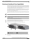
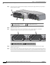
The IPS 4510 ships with one power supply module and one fan module installed, and the IPS 4520 ships
with two power supply modules instead of a power supply module and a fan module. You can replace
the fan module in the IPS 4510 if necessary. The fan module is hot-pluggable. You can install or replace
the fan module without powering down the sensor, as long as the power supply module is active and
functioning correctly. To maintain airflow, both bays must be populated by either a power supply module
and a fan module or two power supply modules.
Note A power supply module is required for the system to operate.
Caution If you remove a power supply or fan module, replace it immediately to prevent disruption of service.
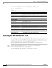
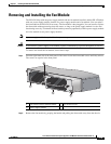
To remove and install the fan module, follow these steps:
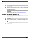
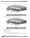
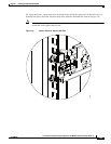
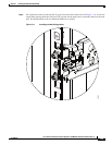
Step 1 From the right-hand side of the back panel of the sensor loosen the fan module screws until they release.
The screws are captive in the front panel.
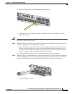
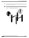
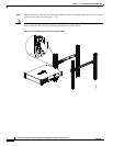
Step 2 Remove the fan module by grasping the handle and pulling the fan module away from the chassis.
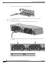
1 Fan module and fan module handle 2 Fan module screws
3 Power supply module
Cisco ASA 1200W AC
100-240V
15.0/8.0.A
56/60Hz
IN
OK
FAN
OK
OUT
FAIL
Cisco-ASA-FAN
253909
2
1
2
3