


1-8
Cisco ME 3800X and ME 3600X Switch Hardware Installation Guide
OL-22168-01
Chapter 1 Product Overview
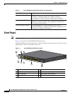
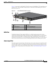
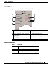
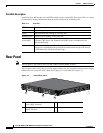
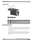
Front Panel
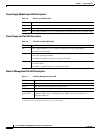
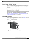
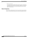
Power Supply Module Input LED Description
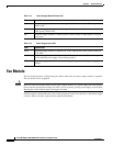
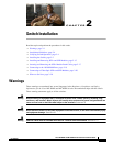
Power Supply and Fan LED Description
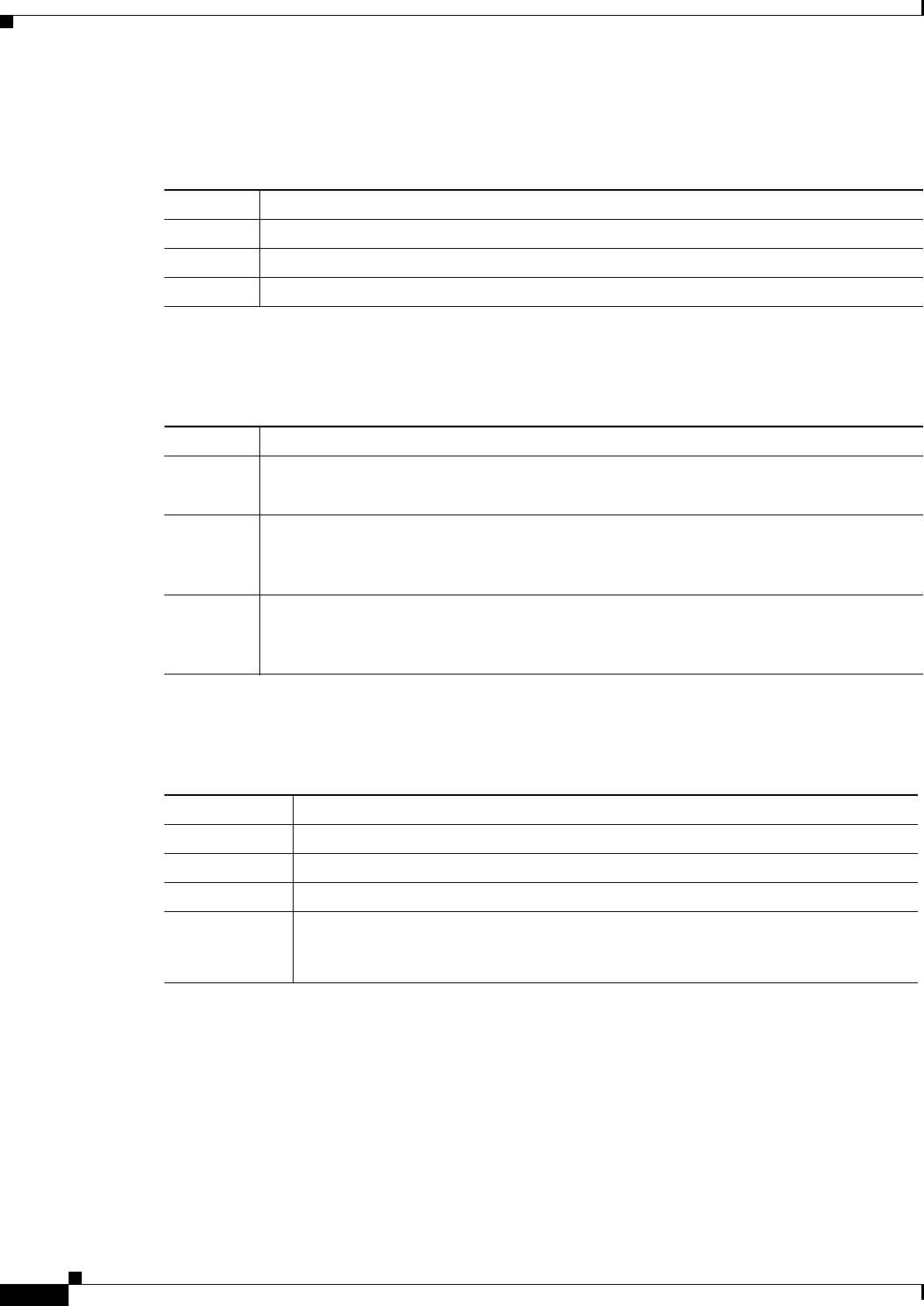
Ethernet Management Port LED Description
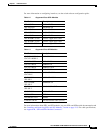
Table 1-5 PS IN 1 and PS IN 2 LEDs
Color System Status
Off Power supply module (1 or 2) is not installed.
Green Power supply module (1 or 2) is installed and receiving power.
Amber Power supply module (1 or 2) is installed but not receiving power in an acceptable range.
Table 1-6 PS/FAN1 and PS/FAN 2 LEDs
Color System Status
Off Power supply module (1 or 2) is either not installed or not producing power.
Fan module is not installed.
Green Power supply module (1 or 2) is installed and producing power in an acceptable range;
the fans are operating normally.
Fan module is installed; the fans are operating normally.
Red Power supply module (1 or 2) is installed but not producing power in an acceptable range,
or a fan has failed.
Fan module is installed, but one of the fans has failed.
Table 1-7 Ethernet Management Port LED
Color System Status
Off No link, or port was administratively shut down.
Green Link present but not sending or receiving data.
Blinking green Activity. Port is sending or receiving data.
Alternating
green/amber
Link fault. Error frames can affect connectivity, and errors such as excessive
collisions, CRC
1
errors, and alignment and jabber errors
2
are monitored for a
link-fault indication.
1. CRC = cyclic redundancy check.
2. Jabber errors occur when data packets exceed the prescribed lengths.