


3-6
Cisco ME 3800X and ME 3600X Switch Hardware Installation Guide
OL-22168-01
Chapter 3 Installing and Removing AC and DC Input Power Supply and Fan Modules
Power Supply and Fan Module Installation
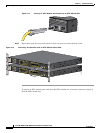
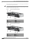
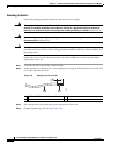
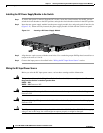
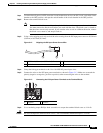
Step 5 (Optional) Attach the power-cord retainer clip to the power supply module and thread the plastic bushing
until it is snug against the plug (Figure 3-7).
Figure 3-7 AC Power Supply Module and Power-Cord Retainer in a Switch
Step 6
Turn on the power at the power source and set the power supply module switch to ON.
Step 7 From the front of the switch, confirm that the PS IN and the PS/FAN LEDs are green. If you can access
the switch rear panel, verify that the PSU and INPUT LEDs are green. See the “Power Supply Module
LEDs” section on page 1-11 for a description of the power supply module LEDs. See the “Switch LED
Panels” section on page 1-7 for system LED descriptions.
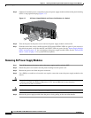
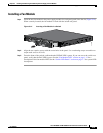
Removing AC Power Supply Modules
Step 1 Turn off the power at its source, and set the power supply module switch to OFF.
Step 2 Detach the power-cord retainer and the plastic bushing from the power cord.
Step 3 Remove the power cord from the power connector.
Step 4 Use a Phillips screwdriver to loosen the two captive screws that secure the power supply module to the
chassis.
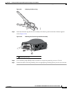
Caution Do not leave the power supply slot open for more than:
- 5 minutes provided the ambient temperature is 25°C and at 5000 feet or lower elevation
- 90 seconds in all other conditions.
Caution Wait 5 minutes prior to reopening a power supply slot.
Step 5 Remove the power supply module from the power slot by pulling on the extraction handle.
278366