


2-19
Cisco ME 3800X and ME 3600X Switch Hardware Installation Guide
OL-22168-01
Chapter 2 Switch Installation
Connecting to the 10/100/1000 Ports
Connecting to the 10/100/1000 Ports
The switch 10/100/1000 ports configure themselves to operate at the speed of attached devices. If the
attached ports do not support autonegotiation, you can explicitly set the speed and duplex parameters.
Connecting devices that do not autonegotiate or that have their speed and duplex parameters manually
set can reduce performance or result in no linkage.
To maximize performance, choose one of these methods for configuring the Ethernet ports:
• Let the ports autonegotiate both speed and duplex.
• Set the port speed and duplex parameters on both ends of the connection.
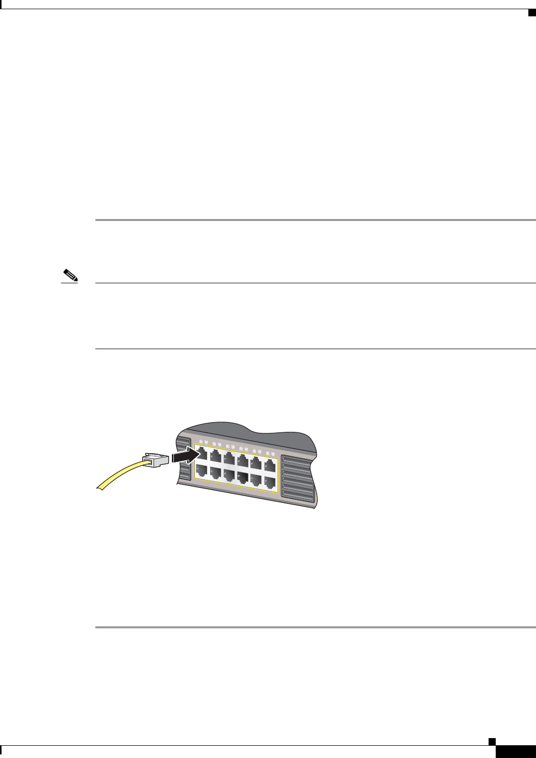
Follow these steps to connect to 10BASE-T, 100BASE-TX, or 1000-BASE-T devices:
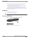
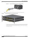
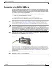
Step 1 When connecting to workstations, servers, and routers, connect a straight-through cable to an RJ-45
connector on the front panel. (See Figure 2-15.) When connecting to switches or repeaters, use a
crossover cable. (See the “Cables and Adapters” section on page B-5 for cable-pinout descriptions.)
Note You can use the mdix auto interface configuration command in the CLI to enable the automatic
medium-dependent interface crossover (auto-MDIX) feature. The switch then detects the required cable
type for copper Ethernet connections and configures the interfaces accordingly. Therefore, you can use
either a crossover or a straight-through cable for connections to a copper 10/100/1000 or 1000BASE-T
SFP module port on the switch, regardless of the type of device on the other end of the connection.
Step 2 Connect the other end of the cable to an RJ-45 connector on the other device. The port LED turns on
when both devices have established link. (See Figure 2-15.)
Figure 2-15 Connecting to an Ethernet Port
The port LED is amber while Spanning Tree Protocol (STP) discovers the topology and searches for
loops. This takes about 30 seconds, and then the port LED turns green. If the port LED does not turn
green, the device at the other end might not be turned on, or there might be a cable problem or a problem
with the adapter installed in the attached device. See Chapter 4, “Troubleshooting,” for solutions to
cabling problems.
Step 3 Reconfigure and reboot the connected device, if necessary.
Step 4 Repeat Steps 1 through 3 to connect each device.
2X
1X
11X
12X
1
1
1
2
3
4
5
6
7
8
9
10
11
12
207933