


3-10
Cisco ME 3800X and ME 3600X Switch Hardware Installation Guide
OL-22168-01
Chapter 3 Installing and Removing AC and DC Input Power Supply and Fan Modules
Power Supply and Fan Module Installation
Installing the DC Power Supply Module in the Switch
Step 1 To ensure that power is removed from the DC circuits, locate the circuit breakers for the DC circuits,
switch the circuit breakers to the OFF position, and tape the circuit-breaker switches in the OFF position.
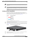
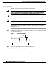
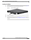
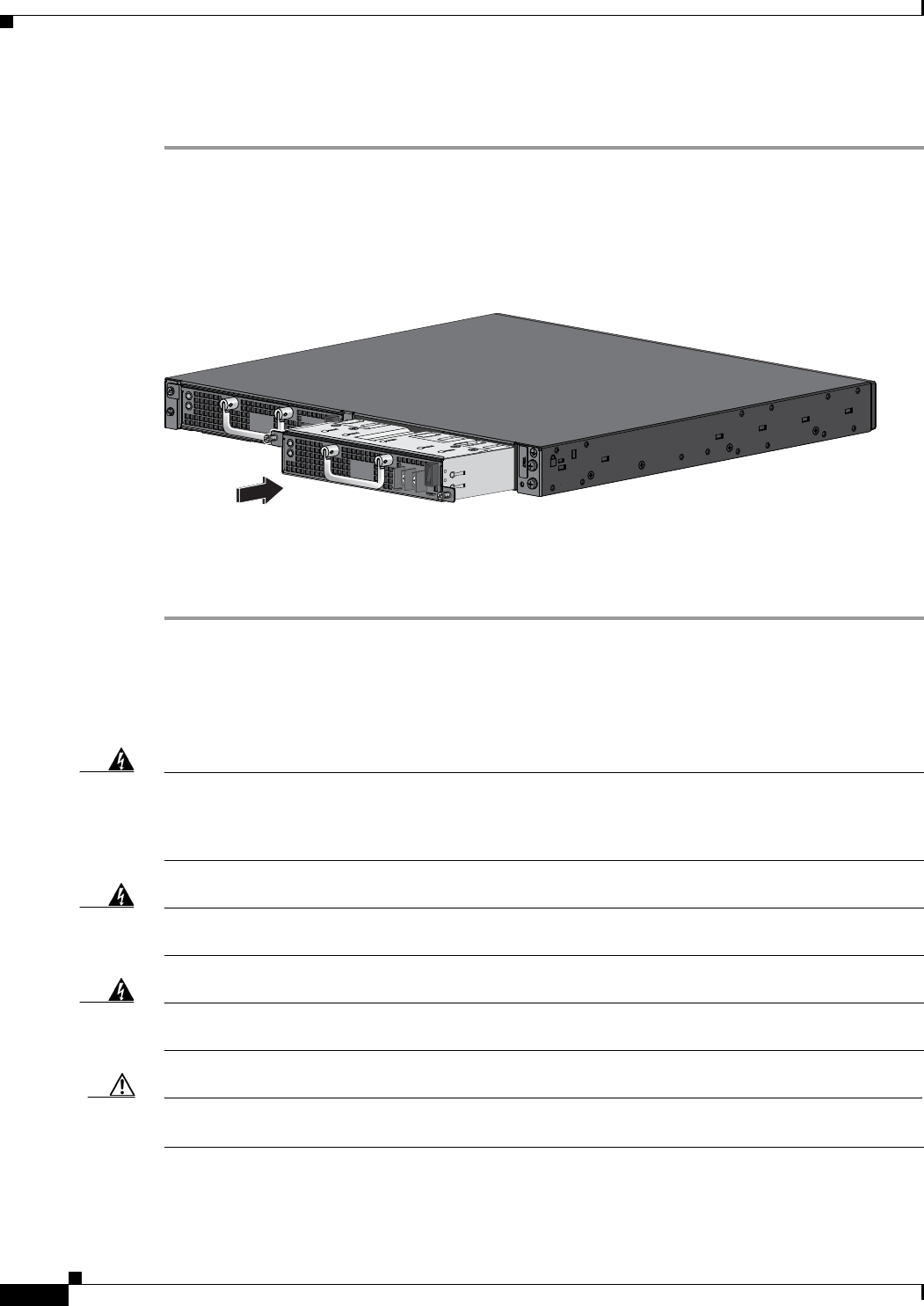
Step 2 Insert the new power supply module into the power supply module slot, and gently push it into the slot
(Figure 3-11). When correctly inserted, the power supply module is flush with the switch rear panel.
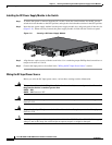
Figure 3-11 Inserting a DC Power Supply Module
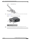
Step 3
Align the two captive screws with the screw holes. Use a ratcheting torque Phillips-head screwdriver to
torque each screw to 10 in-lb.
Step 4 Connect the input power as described in the “Wiring the DC Input Power Source” section.
Wiring the DC Input Power Source
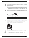
Before you wire the DC input power source, review these warnings and the information:
Warning
This product relies on the building’s installation for short-circuit (overcurrent) protection. Ensure that
the protective device is rated not greater than:
24VDC – 30A
48VDC – 15A
Statement 1005
Warning
A readily accessible two-poled disconnect device must be incorporated in the fixed wiring.
Statement 1022
Warning
Only trained and qualified personnel should be allowed to install, replace, or service this equipment.
Statement 1030
Caution The DC power supply module voltage should be within 18 to 32 VDC or 36 to 72 VDC. If the supply
voltage is not in this range, the switch might not operate properly or might be damaged.
207479
PSU OK
AC
PSU OK
AC