


1-3
Cisco ME 3800X and ME 3600X Switch Hardware Installation Guide
OL-22168-01
Chapter 1 Product Overview
Front Panel
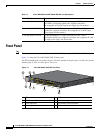
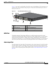
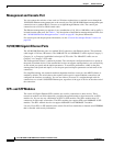
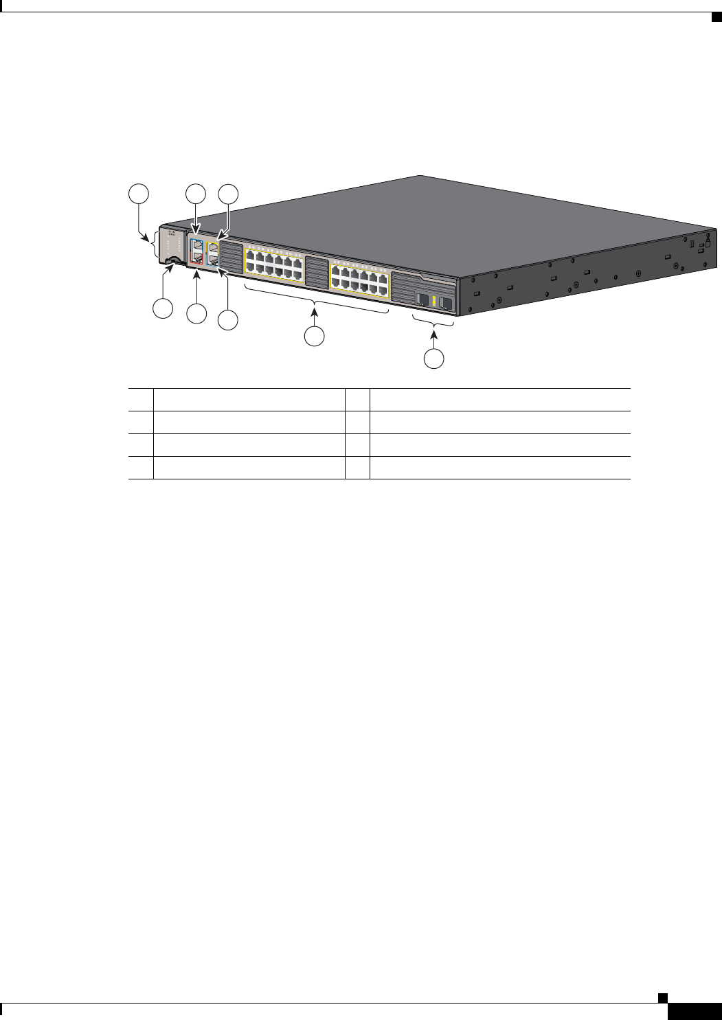
Figure 1-2 shows the Cisco ME-3600X-24TS-M. The copper 10/100/1000Base-T/TX downlink ports are
grouped in pairs. The first member of the pair (port 1) is above the second member (port 2). Port 3 is
above port 4, and so on.
Figure 1-2 Cisco ME-3600X-24TS-M Front Panel
BITS Port
The Building Integrated Timing Supply (BITS) port is an RJ-45 interface that provides external
synchronized clocking through a timing signal generator (TSG). The BITS input is an external timing
reference that must be traceable to a stratum 3 clock or better. The BITS port on the switch can be
configured to accept either a T1 or an E1 framed input. Although this clock input is T1 or E1 framed, it
does not carry data and cannot be used for any other purpose than to derive clocking for the system.
Alarm Input Port
The switch supports four alarm inputs. The alarm input is a dry-contact alarm port. Use the CLI to define
each alarm input to respond to a normally open or closed dry-contact closure and to define the alarm
severity as minor, major, or critical. When a condition triggers an alarm, the console displays an alarm
message, and the corresponding Alarm LED responds (see the “Alarm LEDs Description” section on
page 1-9).
1 LEDs 5 BITS port
2 SD flash card slot 6 Ethernet management port
3 Alarm input port 7 10/100/1000BASE-T/TX ports (downlink)
4 Console port 8 SFP+ module slots (uplink)
207474
ALM 4
SYNC
ALM 2
ALM 1
MGMT
ALM 3
PS/FAN 1
PS/FAN 2
SD CARD
PS IN 2
PS IN 1
SYST
CONSOLE
MGMT
ALARMS
BITS
1
2
2X
1X
11X
12X
13X
14X
23X
24X
1
2
3
4
5
6
7
8
9
10
11
12
13
14
15
16
17
18
19
20
21
22
23
24
5
7
3
6
1
4
2
8