


3-5
Cisco ME 3800X and ME 3600X Switch Hardware Installation Guide
OL-22168-01
Chapter 3 Installing and Removing AC and DC Input Power Supply and Fan Modules
Power Supply and Fan Module Installation
Warning
Do not work on the system or connect or disconnect cables during periods of lightning activity.
Statement 1001
Caution To prevent overheating and to maintain proper air flow, either a power supply module or a fan module
must be installed in each power supply module slot at all times. Never operate the switch for extended
periods of time without either a power supply module or a fan module installed in each power supply
module slot.
Installing an AC Power Supply Module
This procedure is for installing an AC power supply module in the PSU 1 power supply module slot.
Repeat these steps to install a power supply module in the PSU 2 power supply module slot.
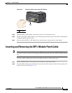
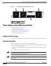
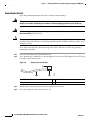
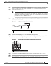
Each AC power input is dedicated to one power supply module (PSU 1 or PSU 2). One AC power input
does not power on both power supply modules at the same time (see Figure 3-5).
Figure 3-5 AC Power Supply Diagram
To install an AC input power supply module, follow these steps:
Step 1 Verify that the power from the power source is off.
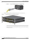
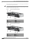
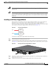
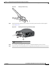
Step 2 Insert the new power supply module in the power supply module slot, and gently push it into the slot
(see Figure 3-6). When correctly inserted, the power supply module is flush with the switch rear panel.
Figure 3-6 Inserting an AC Power Supply Module in a Switch
Step 3 Align the two captive screws with the screw holes in the panel. Use a ratcheting torque screwdriver to
torque each screw to 10 in-lb.
Step 4 Connect the AC power cord to the power supply module and to an AC power outlet.
AC-1
AC-2
PSU-1
PSU-2
280937
207478
PSU OK
AC