


2-11
Cisco ME 3800X and ME 3600X Switch Hardware Installation Guide
OL-22168-01
Chapter 2 Switch Installation
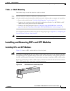
Installing the Switch
Mounting in a Rack
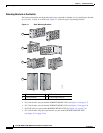
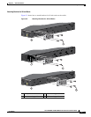
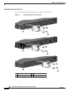
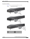
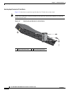
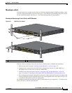
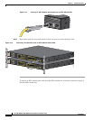
After the brackets are attached on the switch, use the four supplied number-12 Phillips machine screws
to securely attach the brackets to the rack. See Figure 2-6 for standard rack-mounting using the 19-inch,
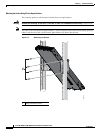
23-inch, and ETSI brackets. See Figure 2-7 for rack-mounting using the angle-bracket.
Mounting the Switch using 19-Inch, 23-Inch, and ETSI Brackets
Figure 2-6 Mounting the Switch
After the switch is mounted in the rack, you need to do these tasks to complete the installation:
• Power on the switch. See the “Verifying Switch Operation” section on page 2-4.
• Connect to the console port, and run the initial configuration. See the Cisco ME 3800X and
ME 3600X Switch Getting Started Guide for instructions.
• Connect to the front-panel ports. See the “Connecting to the 10/100/1000 Ports” section on
page 2-19 and the “Connecting to Fiber-Optic SFP+ and SFP Modules” section on page 2-20.
• We recommend attaching the cable guide to prevent the cables from obscuring the front panel of the
switch and the other devices installed in the rack. Use the supplied black screw shown in Figure 2-6
to attach the cable guide to the left or right bracket.
For configuration instructions about using the CLI setup program, go to Appendix C, “Configuring the
Switch with the CLI-Based Setup Program.”
1 Phillips machine screws 2 Cable guide and screw
ALM 4
SYNC
ALM 2
ALM 1
MGMT
ALM 3
PS/FAN 1
PS/FAN 2
SD CARD
PS IN 2
PS IN 1
SYST
2X
12X 24X
14X
CONSOLE
MGMT
ALARMS
BITS
1
2
1
2
3
4
5
6
7
8
9
10
11
12
13
14
15
16
17
18
19
20
21
22
23
24
ALM 4
SYNC
ALM 2
ALM 1
MGMT
ALM 3
PS/FAN 1
PS/FAN 2
SD CARD
PS IN 2
PS IN 1
SYST
2X
12X
24X
14X
CONSOLE
MGMT
ALARMS
BITS
1
2
1
2
3
4
5
6
7
8
9
10
11
12
13
14
15
16
17
18
19
20
21
22
23
24
1
2
207499