


2-20
Cisco ME 3800X and ME 3600X Switch Hardware Installation Guide
OL-22168-01
Chapter 2 Switch Installation
Connecting to Fiber-Optic SFP+ and SFP Modules
Connecting to Fiber-Optic SFP+ and SFP Modules
Warning
Class 1 laser product.
Statement 1008
Caution Do not remove the rubber plugs from the SFP+ or SFP module port or the rubber caps from the
fiber-optic cable until you are ready to connect the cable. The plugs and caps protect the SFP+ or SFP
module ports and cables from contamination and ambient light.
Before connecting to the SFP+ or SFP module, be sure that you understand the port and cabling
stipulations in the “Installation Guidelines” section on page 2-4 and in the “SFP+ and SFP Modules”
section on page 1-4. See Appendix B, “Connector and Cable Specifications,” for information about the
LC on the SFP+ or SFP module.
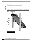
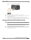
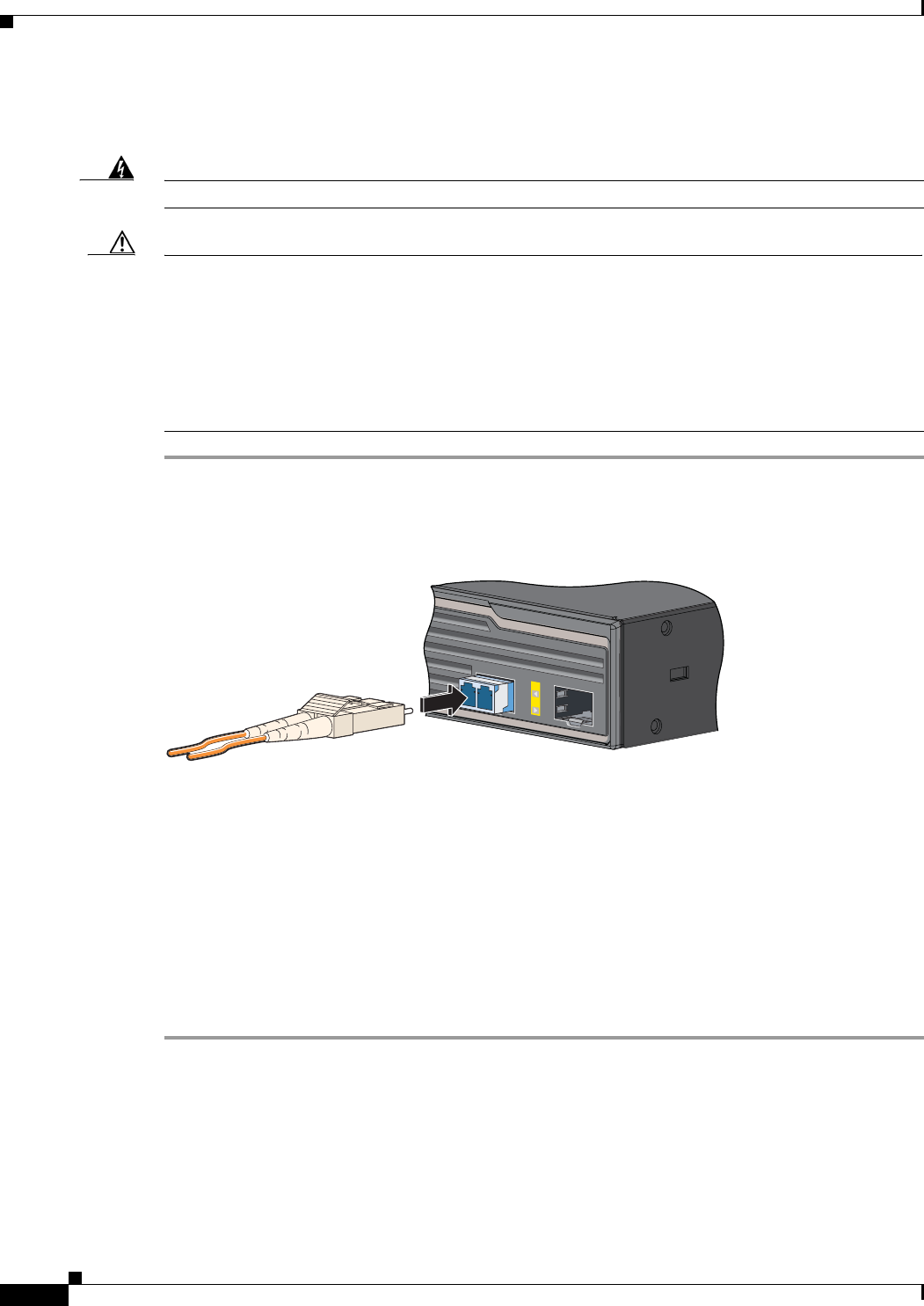
Step 1 Remove the rubber plugs from the module port and fiber-optic cable, and store them for future use.
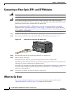
Step 2 Insert one end of the fiber-optic cable into the SFP+ or SFP module port (see Figure 2-16).
Figure 2-16 Connecting to a Fiber-Optic SFP Module Port
Step 3 Insert the other cable end into a fiber-optic connector on a target device.
Step 4 Observe the port status LED.
The LED turns green when the switch and the target device have an established link.
The LED turns amber while the STP discovers the network topology and searches for loops. This process
takes about 30 seconds, and then the port LED turns green.
If the LED is off, the target device might not be turned on, there might be a cable problem, or there might
be problem with the adapter installed in the target device. See Chapter 4, “Troubleshooting,” for
solutions to cabling problems.
Step 5 If necessary, reconfigure and restart the switch or target device.
Where to Go Next
You can use the default configuration or use any of the management options described in the
“Management Options” section on page 1-13 to change the switch settings.
207471
1
2