


3-12
Cisco ME 3800X and ME 3600X Switch Hardware Installation Guide
OL-22168-01
Chapter 3 Installing and Removing AC and DC Input Power Supply and Fan Modules
Power Supply and Fan Module Installation
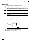
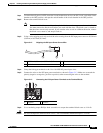
Caution Secure the wires coming from the terminal block so that they cannot be disturbed. For example, use tie
wraps to secure the wires to the rack.
Step 7 After ensuring that all wire connections are secure, reinstall the terminal block cover.
Step 8 Remove the tape from the circuit-breaker switch handle, and move the circuit-breaker handle to ON.
Step 9 Move the DC power supply module switch to ON.
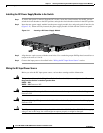
Step 10 From the front of the switch, confirm that the PS IN and the PS/FAN LEDs are green. If you can access
the switch rear panel, verify that the power supply module PSU and INPUT LEDs are green. See the
“Power Supply Module LEDs” section on page 1-11 for a description of the power supply module LEDs.
See the “Switch LED Panels” section on page 1-7 for system LED descriptions
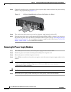
Removing the DC Power Supply Module
Step 1 Move the DC power supply module switch to OFF.
Step 2 Turn off power at the DC circuits. To ensure that power is removed from the DC circuits, locate the
circuit breakers for the DC circuits, switch the circuit breakers to OFF, and tape the circuit-breaker
switches.
Step 3 Remove the terminal block cover from the power supply module terminal blocks.
Step 4 Use a Phillips screwdriver to remove the DC input power wires from the power terminals.
Step 5 Use a Phillips screwdriver to loosen the two captive screws that secure the power supply module to the
switch chassis.
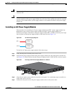
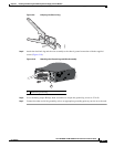
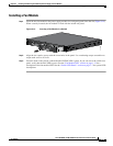
Step 6 Remove the power supply module from the power slot by pulling on the extraction handle.
Caution To prevent overheating and to maintain proper air flow, either a power supply module or a fan module
must be installed in each power supply module slot at all times.