


3-11
Cisco ME 3800X and ME 3600X Switch Hardware Installation Guide
OL-22168-01
Chapter 3 Installing and Removing AC and DC Input Power Supply and Fan Modules
Power Supply and Fan Module Installation
Step 1 To ensure that all power is OFF, locate the circuit breaker that services the DC circuit, switch the circuit
breaker to the OFF position, and tape the switch handle of the circuit breaker in the OFF position.
Step 2 Remove the terminal block cover.
Note The terminal block is covered by a clear plastic block cover that snaps onto the terminal block.
You must remove the block cover before you work with the wires. The block cover is slotted so
that the wires can exit only one end. If you want the wires to exit in a different direction, remove
the block cover, rotate it, and snap it back on.
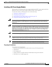
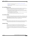
Step 3 Using a wire-stripping tool, strip each of the wires coming from the DC input power source to 0.350 inch
(8.9 mm) ± 0.02 inch (0.5 mm).
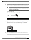
Figure 3-12 Stripping the DC Input Power Source Wire
Step 4
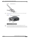
Crimp the fork-type terminals to the 14 or 16 AWG DC power input wires.
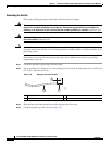
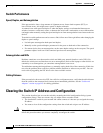
Step 5 Connect the wires to the DC input power terminals as shown in Figure 3-13. Make sure to match the
polarity (negative to negative, positive to positive) when connecting the wires to the terminal.
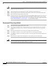
Figure 3-13 Connecting the DC Input Power Terminals to the Terminal Blocks
Step 6 Use a ratcheting torque Phillips-head screwdriver to torque the terminal-block screw to 14 in-lb.
Caution Do not overtorque the terminal-block screws. The recommended maximum torque is 14 in-lb.
1 0.350 inch (8.9 mm) ± 0.02 inch (0.5 mm) 3 Wire lead
2 Insulation
254820
2
1
3
1 Negative 2 Positive
207935
21