


1-4
Cisco uBR10012 Universal Broadband Router Troubleshooting Guide
OL-1237-01
Chapter 1 Basic Troubleshooting Tasks and Startup Issues
Displaying System Environment Information
Displaying System Environment Information
Use the show environment command to display the basic system environment status, to verify the
following:
• Make sure the system operating temperature is equal to or less than 41° F at the inlet and 104° F
degrees at the core (5° C and 40° C).
• That the fan assembly module is installed in the chassis and operating properly.
• Report the operational status of the PEMs and blower
If the operating temperature is not between 41° F and 104° F, refer to the “Fan Assembly Module Faults”
section on page 2-7.
The following example is sample output from the show environment command for a system with two
DC PEMs installed:
UBR10K-ROUTER1# show environment
Temperature normal:chassis inlet measured at 29C/84F
Temperature normal:chassis core measured at 39C/98F
Fan: OK
Power Entry Module 0 type DC status: OK
Power Entry Module 0 Power: 555w
Power Entry Module 0 Voltage: 62v
Power Entry Module 1 type DC status: OK
Power Entry Module 1 Power: 558w
Power Entry Module 1 Voltage: 62v
UBR10K-ROUTER1#
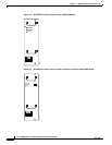
Hardware Troubleshooting Flowchart
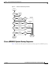
Use Figure 1-1 to determine which component of your Cisco uBR10012 router is malfunctioning.
Figure 1-1 describes a series of hardware dependent startup events that must take place for a
Cisco uBR10012 router to allow the passage of IP traffic. At each main point of the flowchart, there are
pointers to the chapters in this guide that describe how to troubleshoot individual pieces of hardware.
Note This flowchart does not address software configuration problems.