


2-2
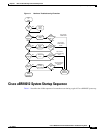
Cisco uBR10012 Universal Broadband Router Troubleshooting Guide
OL-1237-01
Chapter 2 PEM Faults and Fan Assembly Failures
AC PEM Faults
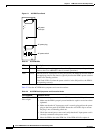
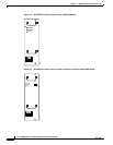
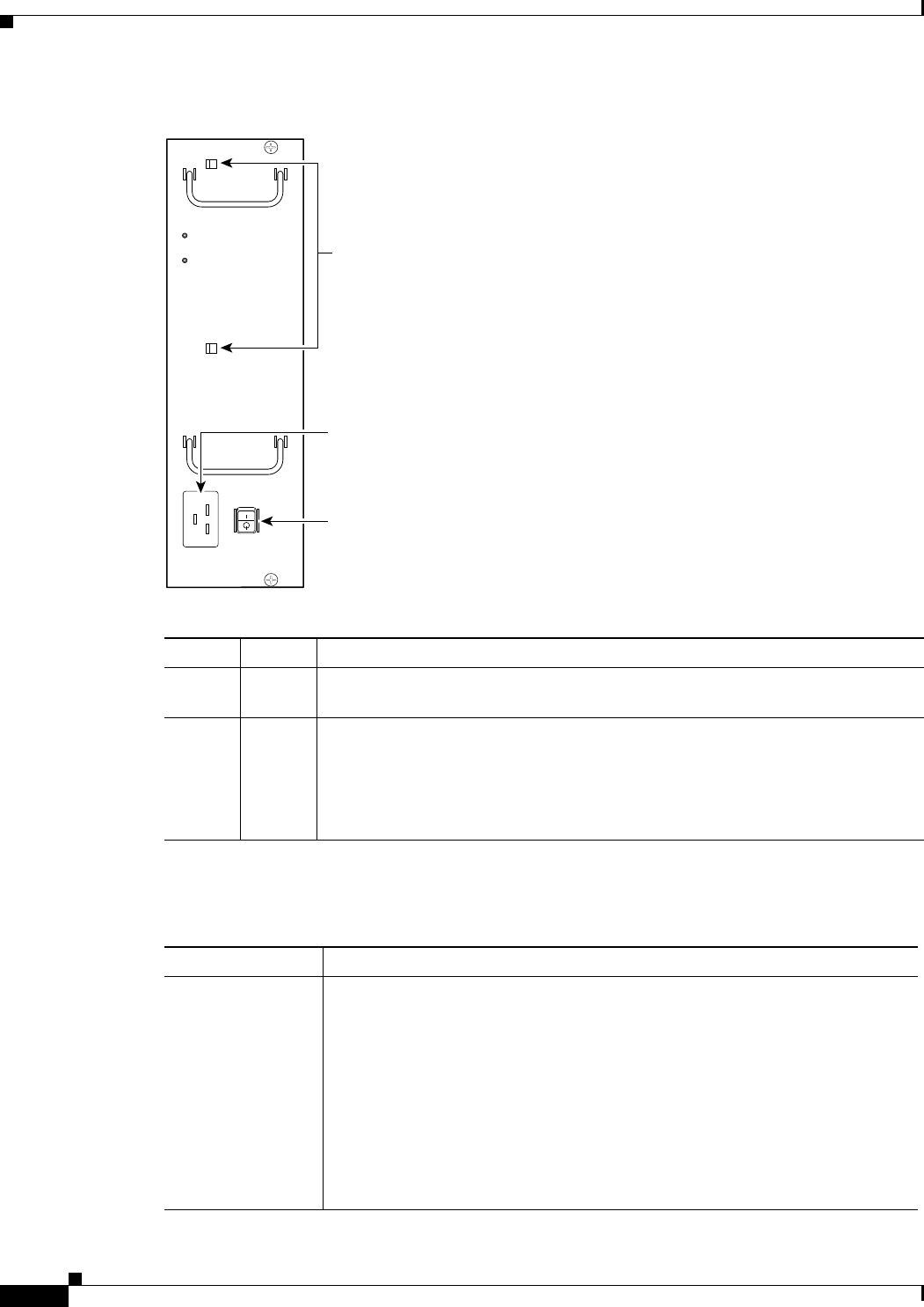
Figure 2-1 AC PEM Front Panel
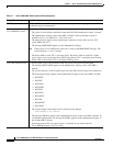
Table 2-2 lists the AC PEM fault symptoms and corrective actions.
Table 2-1 AC PEM LEDs
LED Color Description
Power Green The PEM is on, is receiving power from the AC power source, and is providing
power to the Cisco uBR10012 chassis (normal operations).
Fault Yellow Indicates that AC-input power is being received by the PEM, but that the PEM is
not supplying power to the chassis, typically because the PEM’s power switch is
turned to the standby position.
If the Fault LED is lit when the power switch is in the ON position, the PEM is
not operating correctly.
62520
POWER
FAULT
AC power
cord clips
AC power switch
AC power plug
Table 2-2 AC PEM Fault Symptoms and Corrective Action
Fault Symptom Corrective Action
Green LED on PEM
fails to light
1. Make sure the power switch on the PEM is turned to the ON position.
2. Make sure the PEM is properly seated and that its captive screws have been
tightened.
3. Make sure that the AC-input power cord is securely plugged into the power
plug on the front panel of the PEM. Secure the cord in the clips to ensure
the plug is not accidentally pulled out.
4. Check the external power source and verify that the AC-input power cord is
correctly connected to the power outlet.
5. Move the PEM to the other PEM slot. If the PEM still fails, replace it.