


2-3
Cisco uBR10012 Universal Broadband Router Troubleshooting Guide
OL-1237-01
Chapter 2 PEM Faults and Fan Assembly Failures
DC PEM Faults
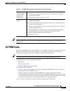
Tip Securely tighten the captive screws on your PEMs to prevent heightened levels of electromagnetic
interference.
DC PEM Faults
On the Cisco uBR10012 router, two DC PEMs are in a redundant configuration, which allows one DC
PEM to fail without affecting system operations. A single PEM can usually power the router for
sufficient time to request and install a new PEM to replace the one that failed.
Tip To quickly check the functional status of your PEMs, use the show environment command.
DC PEM faults can occur for the following reasons:
• PEM failure
• Reversed power cables
• Backplane interface failures or damage
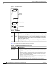
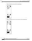
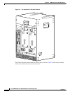
Two models of the DC PEM exist.
• Figure 2-2 shows the front panel of the original DC PEM (UBR10-PWR-DC) that was initially
produced for the Cisco uBR10012 router.
• Figure 2-3 shows the front panel of the DC PEM that is currently being produced for the
Cisco uBR10012 router. The new model of the DC PEM (UBR10-PWR-DC-M) is identical in form
and function to the first version, except that it includes a connector on the front panel for connecting
to the alarm status connectors on the optional 2400-watt AC-input power shelf.
Table 2-3 describes the indicators on the front panel of both models of DC PEM.
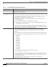
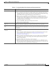
PEM experiences
problems in one
slot but operates
normally in a
different slot
1. Ensure that the input power to both slots is correct.
2. Verify that no connections have been made to the DC-power connectors
underneath each PEM.
3. If the problem persists, contact Cisco TAC.
Fault LED is lit
yellow
1. Verify that no connections have been made to the DC-power connectors
underneath each PEM.
2. Verify that the PEM is fully inserted into the power bay and that its captive
screws have been tightened.
3. Check to see if the power switch is set to the standby position. If so, set the
switch to the ON position.
4. If the problem persists, flip the power switch on the PEM to the standby
position, wait several seconds, and then back to the ON position.
5. Replace PEM with a known good replacement.
6. Contact Cisco TAC.
Table 2-2 AC PEM Fault Symptoms and Corrective Action (continued)