


VIP-FE-TX/4E Installation and Configuration 17
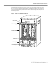
Versatile Interface Processor Functions
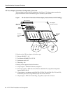
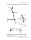
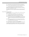
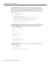
Figure 9 shows proper handling of an interface processor during installation.
Figure 9 Handling Processor Modules for Installation and Removal (Horizontal Orientation Shown)
To remove a VIP, follow these steps:
Step 1 If you are replacing a failed VIP, disconnect all cables from the VIP ports; however, if you
are only moving a VIP to another slot, this step is not necessary.
Step 2 Use a screwdriver to loosen the captive installation screws at both ends of the VIP.
(See Figure 8.)
Caution Always use the ejector levers to remove or install the VIP. Failure to do so can cause
erroneous system error messages indicating a board failure.
Step 3 Place your thumbs on the ejector levers and simultaneously pull both of the ejectors
outward (in the opposite direction from that show in Figure 8c) to release the VIP from the
backplane connector.
Step 4 Use the VIP handle to carefully pull the VIP straight out of the slot, keeping your other
hand under the carrier to guide it. (See Figure 9.) Keep the VIP parallel to the backplane.
Step 5 Place the removed VIP on an antistatic mat or foam pad, or place it in an antistatic bag if
you plan to return it to the factory.
Step 6 If the interface processor slot is to remain empty, install a filler (MAS7K-BLANK) to keep
dust out of the chassis and to maintain proper air flow inside the chassis. Do not leave the
interface processor slot open. Immediately proceed to the section “Installing a VIP.”
H4714
Captive installation
screws