


VIP-FE-TX/4E Installation and Configuration 35
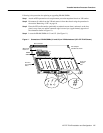
VIP Port Adapter Functions
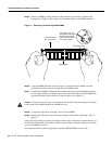
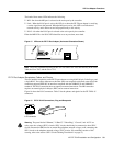
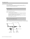
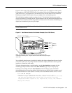
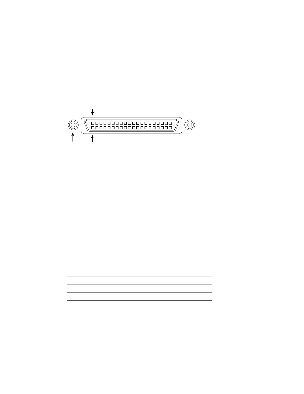
The MII receptacle uses 2-56 screw-type locks, called jackscrews (shown in Figure 19), to secure
the cable or transceiver to the MII port. MII cables and transceivers have knurled thumbscrews
(screws you can tighten with your fingers) that you fasten to the jackscrews on the FE-TX port
adapter’s MII connector. Use the jackscrews to provide strain relief for your MII cable. (The RJ-45
modular plug has strain relief functionality incorporated into the design of its standard plastic
connector.) Figure 19 shows the MII female connector.
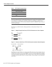
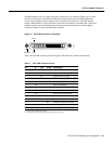
Figure 19 FE-TX MII Connection, Receptacle
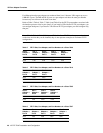
Table 4 lists the MII connector pinout and signals. MII cables are available commercially.
Table 4 FE-TX MII Connector Pinout
Pin
1
1. Any pins not indicated are not used.
In Out In/Out Description
14–17 – Yes – Transmit Data (TxD)
12 Yes – – Transmit Clock (Tx_CLK)
2
2. Tx_CLK and Rx_CLK are generated by the external transceiver.
11 – Yes – Transmit Error (Tx_ER)
13 – Yes – Transmit Enable (Tx_EN)
3 – Yes – MII Data Clock (MDC)
4–7 Yes – – Receive Data (RxD)
9 Yes – – Receive Clock (Rx_CLK)
10 Yes – – Receive Error (Rx_ER)
8 Yes – – Receive Data Valid (Rx_DV)
18 Yes – – Collision (COL)
19 Yes – – Carrier Sense (CRS)
2 – – Yes MII Data Input/Output (MDIO)
22–39 – – – Common (ground)
1, 20, 21, 40 – – – +5.0 volts (V)
a
ckscrew Pin 1
Pin 21
H2943