


VIP-FE-TX/4E Installation and Configuration 39
VIP Port Adapter Functions
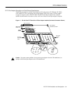
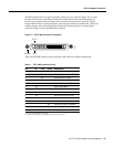
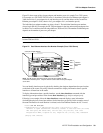
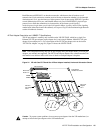
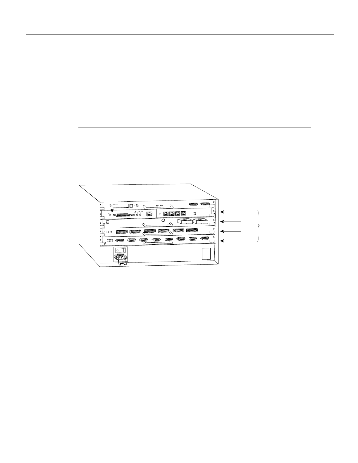
Figure 22 shows some of the slot port adapter and interface ports of a sample Cisco 7505 system.
For example, on a FE-TX/FE-TX VIP in slot 3, the address of the first Fast Ethernet port adapter is
3/0/0 (chassis slot 3, port adapter slot 0, and interface port 0), and the address of the second Fast
Ethernet port adapter is 3/1/0 (chassis slot 3, port adapter slot 1, and interface port 0).
The individual port adapter numbers are always 0 and 1. The individual interface port numbers
always begin with 0. For example, the FE-TX port adapters in the first and second port adapter slots
in chassis slot 3 would have the following addresses: 3/0/0 and 3/1/0. The number of additional ports
depends on the number of ports on a port adapter.
Note If you remove the VIP from slot 3 and install it in slot 2, the addresses of those same ports
become 2/0/0 and 2/1/0.
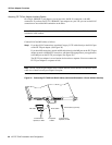
Figure 22 Fast Ethernet Interface Port Number Example (Cisco 7505 Shown)
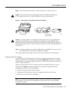
You can identify interface ports by physically checking the slot/port adapter/interface port location
on the back of the router or by using software commands to display information about a specific
interface or all interfaces in the router.
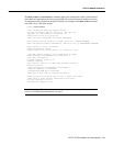
To display information about a specific interface, use the show interfaces command with the
interface type and port address in the format show interfaces [type slot/port adapter/port].
Following is an example of how the show interfaces command displays status information
(including the physical slot and port address) for the interface you specify. In this example, most of
the status information for each interface is omitted, and a Fast Ethernet interface in slot 3 is used.
Router# sh int fa 3/0/0
FastEthernet3/0/0 is administratively down, line protocol is down
Hardware is cyBus FastEthernet Interface, address is 0000.0ca5.2380 (bia 0000)
MTU 1500 bytes, BW 100000 Kbit, DLY 100 usec, rely 255/255, load 1/255
Encapsulation ARPA, loopback not set, keepalive set (10 sec), hdx, 100BaseTX
(display text omitted)
H5922
Slot 0
Slot 1
Slot 2
Slot 3
Interface
processor
slots
EJECT
SLOT 0
SLOT 1
NORMAL
CPU HALT
RESET
CONSOLE
ROUTE SWITCH PROCESSOR
AUX.
ENABLE
3/0/0 (FE-TX port adapter)
Note: The MII and RJ-45 interface ports on the first port adapter are both
numbered as interface port 0. Only one of them can be used on each port adapter,
at one time.
0
1
2
3
LINK
0
1
2
3
ETHERNET 10BT