


VIP-FE-TX/4E Installation and Configuration 47
VIP Port Adapter Functions
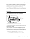
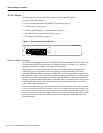
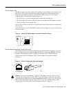
4E Port Adapter LEDs
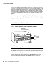
The 4E port adapter contains the enabled LED, standard on all port adapters, and a one status LED
for each port. After system initialization, the enabled LED goes on to indicate that the 4E port
adapter has been enabled for operation. (The LEDs are shown in Figure 25.) The following
conditions must be met before the enabled LED goes on:
• The 4E interface is correctly connected to the backplane and receiving power.
• The 4E-equipped VIP contains a valid microcode version that has been downloaded successfully.
• The bus recognizes the 4E-equipped VIP.
If any of these conditions is not met, or if the initialization fails for other reasons, the enabled LED
does not go on.
When an RJ-45 port is active, its link LED is on when the 4E port adapter is receiving a carrier signal
from the network.
Figure 25 LEDs on the 4E Port Adapter (Horizontal Orientation Shown)
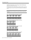
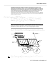
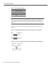
4E Port Adapter Receptacles, Cables, and Pinouts
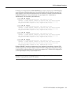
The interface connectors on the 4E port adapter are four individual RJ-45 receptacles. You can use
all four simultaneously. Each connection supports IEEE 802.3 and Ethernet 10BASE-T interfaces
compliant with appropriate standards. The RJ-45 connections require external transceivers.
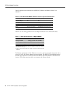
Figure 26 shows the RJ-45 connectors. Table 12 lists the pinouts and signals for the RJ-45
connectors.
Figure 26 4E RJ-45 Connections, Plug and Receptacle
Warning
The ports labeled “Ethernet,” “10BaseT,” “Token Ring,” “Console,” and “AUX” are
safety extra-low voltage (SELV) circuits. SELV circuits should only be connected to other SELV
circuits. Because the BRI circuits are treated like telephone-network voltage, avoid connecting the
SELV circuit to the telephone network voltage (TNV) circuits. (For translated versions of this
warning, refer to the section “SELV Circuit Warning Translations” on page 57.)
ENABLED
H4492
0
2
1
3
LINK
3
H2936
8 7 6 5 4 3 2 1
J
-
45 connector