


18 VIP-FE-TX/4E Installation and Configuration
Versatile Interface Processor Functions
Installing a VIP
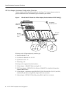
The VIP slides into the open interface processor slot and connects directly to the backplane. The
interface processors are keyed to guide pins on the backplane, so the VIP can be installed only in an
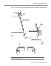
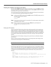
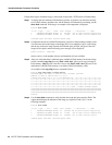
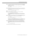
interface processor slot. Figure 8 shows the functional details of inserting an interface processor and
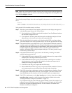
using the ejector levers. Figure 9 shows proper handling of an interface processor during installation.
Caution Remove or insert only one interface processor at a time. Allow at least 15 seconds for the
system to complete its discovery and initialization before removing or inserting another interface
processor. Disrupting the sequence before the system has completed verification can cause the
system to interpret hardware failures.
Follow these steps to install a VIP:
Step 1 Ensure that a console terminal is connected to the console port (on the RP or RSP) and that
your console is turned ON.
Step 2 Hold the VIP handle with one hand and place your other hand under the carrier to support
the VIP and guide it into the slot. (See Figure 9.) Avoid touching the card or any connector
pins.
Caution To prevent ESD damage, handle interface processors by the handles and carrier edges
only.
Note The processor modules are oriented horizontally in the Cisco 7010 and Cisco 7505, and
vertically in the Cisco 7000, the Cisco 7507, and the Cisco 7513.
Step 3 Place the back of the VIP in the slot and align the notch on the carrier with the groove in
the slot. (See Figure 8.)
Step 4 While keeping the VIP parallel to the backplane, carefully slide it into the slot until the back
of the faceplate makes contact with the ejector levers, then stop. (See Figure 8b.)
Caution Always use the ejector levers when installing or removing processor modules. A module
that is partially seated in the backplane will cause the system to hang and subsequently crash, and
shoving or slamming the interface processor into the slot can damage the backplane pins and board.
Step 5 Using your thumbs, simultaneously push both ejector levers inward until the VIP is pushed
entirely into its slot. (See Figure 8c.)
Step 6 To ensure that EMI shielding is properly maintained for the chassis, immediately tighten
both of the captive installation screws.