


VIP-FE-TX/4E Installation and Configuration 51
VIP Port Adapter Functions
Selecting Chassis Slot, Port Adapter, and Ethernet 10BASE-T Interface Port Numbers
The following section describes how to identify chassis slot, port adapter, and Ethernet 10BASE-T
interface port numbers.
Note Although the processor slots in the seven-slot Cisco 7000 and 13-slot Cisco 7513 are
vertically oriented and those in the five-slot Cisco 7010 and Cisco 7505 are horizontally oriented, all
models use the same method for slot and port numbering. (Refer to Figure 2, Figure 3, Figure 4,
Figure 5, or Figure 6 for interface processor slot orientation in your chassis.)
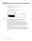
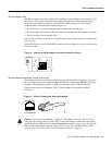
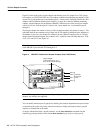
In the router, physical port addresses specify the actual physical location of each interface port on
the router interface processor end. (See Figure 22.) This address is composed of a three-part number
in the format chassis slot number/port adapter number/interface port number.
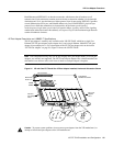
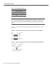
The first number identifies the chassis slot in which the VIP is installed (as shown in the example
system in Figure 31). The second number identifies the physical port adapter number on the VIP, and
is either 0 or 1. The interface ports on each 4E port adapter are always numbered in sequence as
interface 0 through 3.
Interface ports on the VIP maintain the same address regardless of whether other interface
processors are installed or removed. However, when you move a VIP to a different slot, the first
number in the address changes to reflect the new slot number.