


34 VIP-FE-TX/4E Installation and Configuration
VIP Port Adapter Functions
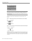
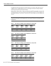
Table 3 FE-TX RJ-45 Connector Pinout
Note Referring to the RJ-45 pinout in Table 3, proper common-mode line terminations should be
used for the unused Category 5, UTP cable pairs 4/5 and 7/8. Common-mode termination reduces
the contributions to electromagnetic interference (EMI) and susceptibility to common-mode
sources. Wire pairs 4/5 and 7/8 are actively terminated in the RJ-45, 100BASE-TX port circuitry in
the FE-TX port adapter.
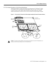
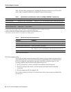
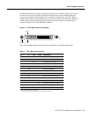
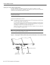
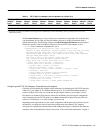
Depending on your RJ-45 interface cabling requirements, use the pinouts in Figure 17 and
Figure 18.
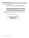
Figure 17 Straight-Through Cable Pinout, FE-TX RJ-45 Connection to a Hub or Repeater
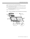
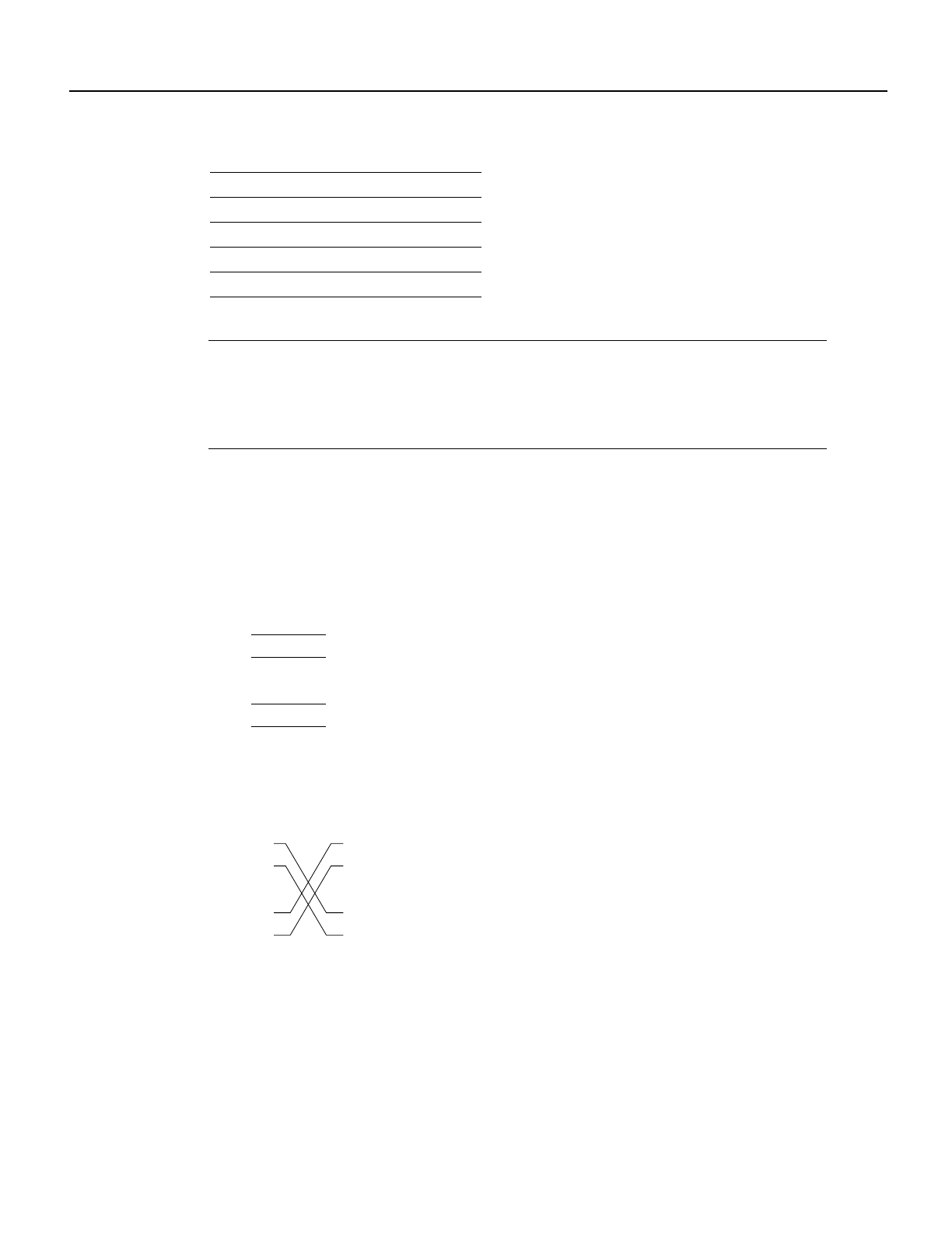
Figure 18 Crossover Cable Pinout, FE-TX RJ-45 Connections between Hubs and Repeaters
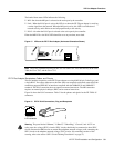
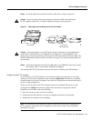
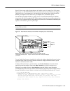
Depending on the type of media you use between the MII connection on the port adapter and your
switch or hub, the network side of your 100BASE-T transceiver should be appropriately equipped:
with ST-type connectors (for optical fiber), BNC connectors, and so forth. Figure 19 shows the pin
orientation of the female MII connector on the port adapter. The port adapters are field-replacable
units (FRUs).
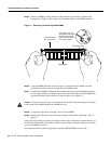
Pin Description
1 Receive Data + (RxD+)
2 RxD–
3 Transmit Data + (TxD+)
6 TxD–
Hub or repeater
F
EIP
TxD+
TxD–
RxD+
RxD–
5 RxD+
6 RxD–
3 TxD+
4 TxD–
H3137
u
b or LAN switch
3 TxD+
6 TxD–
1 RxD+
2 RxD–
3 TxD+
6 TxD–
1 RxD+
2 RxD–
H3138
Hub or LAN switch