


48 VIP-FE-TX/4E Installation and Configuration
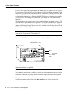
VIP Port Adapter Functions
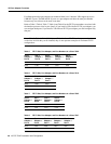
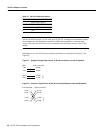
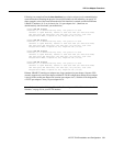
Table 12 4E RJ-45 Connector Pinout
Note Referring to the RJ-45 pinout in Table 12, proper common-mode line terminations should be
used for the unused Category 5, UTP cable pairs 4/5 and 7/8. Common-mode termination reduces
the contributions to electromagnetic interference (EMI) and susceptibility to common-mode
sources. Wire pairs 4/5 and 7/8 are actively terminated in the RJ-45 port circuitry in the 4E port
adapter.
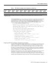
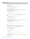
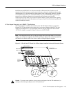
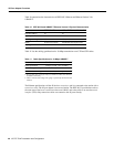
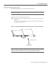
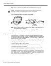
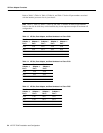
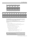
Depending on your 4E, RJ-45 interface cabling requirements, use the pinouts in Figure 27 and
Figure 28.
Figure 27 Straight-Through Cable Pinout, 4E RJ-45 Connection to a Hub or Repeater
Figure 28 Crossover Cable Pinout, 4E RJ-45 Connections Between Hubs and Repeaters
Pin Description
1 Receive Data + (RxD+)
2 RxD–
3 Transmit Data + (TxD+)
6 TxD–
Hub or repeater
F
EIP
TxD+
TxD–
RxD+
RxD–
5 RxD+
6 RxD–
3 TxD+
4 TxD–
H3137
u
b or LAN switch
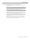
3 TxD+
6 TxD–
1 RxD+
2 RxD–
3 TxD+
6 TxD–
1 RxD+
2 RxD–
H3138
Hub or LAN switch