


16
Chapter 4: Connecting the Wireless-G Router for Mobile Broadband
Placement Options
Wireless-G Router for Mobile Broadband
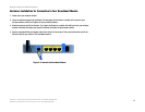
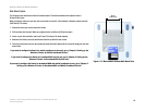
Wall-Mount Option
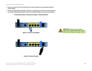
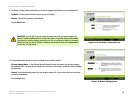
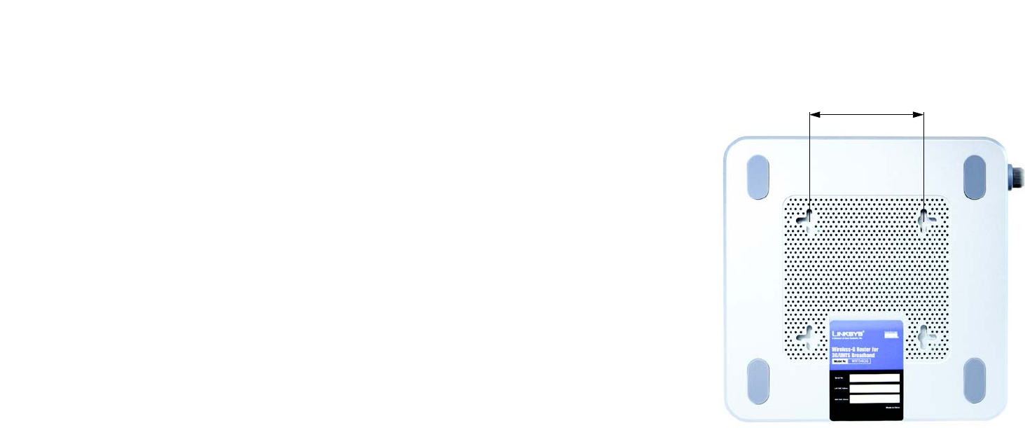
The Router has four wall-mount slots on its bottom panel. The distance between two adjacent slots is
68 mm (2.68 inches).
Before you begin, make sure you have two screws that are size #4—this indicates a diameter measurement of
2.845 mm (0.112 inches).
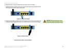
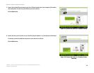
1. Determine where you want to mount the Router.
2. Drill two holes into the wall. Make sure adjacent holes are 68 mm (2.68 inches) apart.
3. Insert a screw into each hole, and leave 5 mm (0.2 inches) of its head exposed.
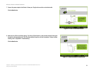
4. Maneuver the Router so the top wall-mount slots line up with the two screws.
5. Place the wall-mount slots over the screws and slide the Router down until the screws fit snugly into the wall-
mount slots.
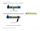
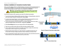
If you want to configure the Router for mobile broadband service only, go to “Chapter 5: Setting up the
Wireless-G Router for Mobile Broadband Service.”
If you want to configure the Router for broadband WAN service only, go to “Chapter 6: Setting up the
Wireless-G Router for Broadband WAN Service Only.”
If you want to configure the Router for broadband WAN and mobile broadband service, go to “Chapter 7:
Setting up the Wireless-G Router for Broadband WAN and Mobile Broadband Service.”
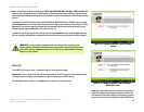
Figure 4-11: Measurement between Wall-Mount Slots
68 mm
(2,68 inches)