


— 34 —
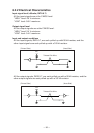
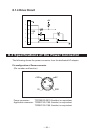
7.3 Description of Input and Output Signals
7.3.1 Input and Output Signals
(1) RD
This is a serial reception data signal. When a framing error, overrun error or
parity error occurs, the data containing the error is printed as a “?”.
(2) DTR, RTS
When this signal is Ready, you can write data or commands into the input buffer.
If you do so while the signal is Busy, an overrun error occurs, and the previously
written data will be ignored. Data can be written into the input buffer even during
printing. A Busy signal is also issued at the time of power-on, test printing, on-
line communication, and resetting.
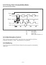
(3) TD
As data is received, the remaining capacity of the printer’s input buffer decreases.
When it becomes less than 128(10) bytes, a DC3 (13H) (Data reception disable
signal) is output to the host computer. On the other hand, when the remaining
capacity of the input buffer increases to 256(20) or more bytes, a DC1 (11H)(Data
reception enable signal) is output to the host computer.
Note: The values in ( ) are for when the 72 bytes of the input buffer is selected by
DIP switches.
(4) DSR
During status information transmission, if DTR/DSR control is selected, the host
computer transfers data to the printer after checking this signal is a space. If DTR/
DSR control is not selected, the host computer ignores this signal and sends data
to the printer. Also, this signal can be used as a reset signal after switching a DIP
switch. (See “5.2 Table for Setting DIP Switches”.) When the pulse width of the
signal is 1 ms or longer, a reset will be applied.
(5) INIT
This signal can be used as a reset signal after switching a DIP switch. (See “5.2
Table for Setting DIP Switches”.) When the pulse width of the signal is 1 ms or
longer in space state, a reset will be applied.
(6) FG
This is a Frame Ground signal.
(7) GND
This is a common ground on circuits.