


Appendixes
68
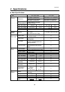
2 Specifications
• Interface Specifications
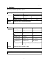
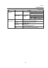
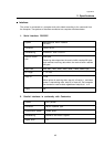
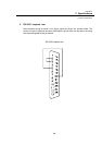
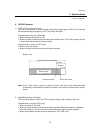
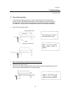
5. Interface pin assignment
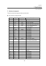
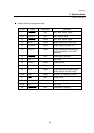
The serial and parallel pin assignment tables are shown below.
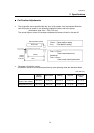
Serial interface pin assignment table
Pin No. Signal Input/Output Description
1 F.GND Output Frame ground
2 TXD Output RS-232C output data
3 RXD Input RS-232C input data
4 RTS Output RS-232C (pull up to +5V with 2 KΩ]
5 CTS Input RS-232C data transmission on
computer enabled
6NC − Not connected
7 S.GND Output Signal ground
8NC − Not connected
9NC − Not connected
10 NC − Not connected
11 NC − Not connected
12 NC − Not connected
13 L.GND Output Control system ground
14 VCCs Output Control system power +5 V
(max. service current 0.05A)
15 NC − Not connected
16 NC − Not connected
17 NC − Not connected
18 NC − Not connected
19 NC − Not connected
20 DTR Output RS-232C printer data receiving
enabled
21 NC − Not connected
22 NC − Not connected
23 NC − Not connected
24 NC − Not connected
25 NC − Not connected