


Technical Reference Guide
Compaq Deskpro EXS and Workstation 300 Personal Computers
Featuring the Intel Pentium 4 Processor
First Edition - December 2000
5-29
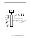
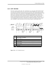
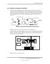
5.8.3 AC97 LINK BUS
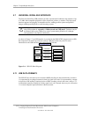
The audio controller and the audio codec communicate over a five-signal AC97 Link Bus (Figure
5-12). The AC97 Link Bus includes two serial data lines (SD OUT/SD IN) that transfer control
and PCM audio data serially to and from the audio codec using a time-division multiplexed (TDM)
protocol. The data lines are qualified by a 12.288 MHz BIT_CLK signal driven by the audio
codec. Data is transferred in frames synchronized by the 48-KHz SYNC signal, which is derived
from the clock signal and driven by the audio controller. The SYNC signal is high during the
frame’s tag phase then falls during T17and remains low during the data phase. A frame consists of
one 16-bit tag slot followed by twelve 20-bit data slots. When asserted (typically during a power
cycle), the RESET- signal (not shown) will reset all audio registers to their default values.
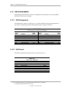
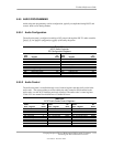
Slot Description
0 Bit 15: Frame valid bit
Bits 14-3: Slots 1-12 valid bits
Bits 2-0: Codec ID
1 Command address: Bit 19, R/W; Bits 18..12, reg. Index; Bits 11..0, reserved.
2 Command data
3 Bits 19-4: PCM audio data, left channel (SD OUT, playback; SD IN, record)
Bits 3-0 all zeros
4 Bits 19-4: PCM audio data, right channel (SD OUT, playback; SD IN, record)
Bits 3-0 all zeros
5 Modem codec data (not used in this system)
6-11 Reserved
12 I/O control
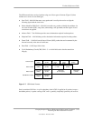
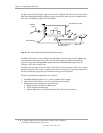
Figure 5-10. AC’97 Link Bus Protocol
Bit 0 Bit 0 Bit 0
T1 T2
3
BIT_CLK
(12.288 MHz)
Codec
Ready
Bit 19 Bit 18 Bit 19 Bit 18 Bit 19
SYNC
(48 KHz)
SD OUT
or SD IN
T18 T19
T38 T39 T58
Slot 0
(Tag)
Slot 1
(Data)
Slot 2
(Data)
Bit 15 Bit 14