


Technical Reference Guide
Compaq Deskpro EXS and Workstation 300 Personal Computers
Featuring the Intel Pentium 4 Processor
First Edition - December 2000
6-3
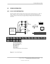
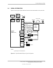
6.2.2 POWER CONTROL
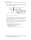
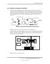
The power supply assembly is controlled digitally by the PS On signal (Figure 7-1). When PS On
is asserted, the Power Supply Assembly is activated and all voltage outputs are produced. When
PS On is de-asserted, the Power Supply Assembly is off and all voltages (except +3.3 AUX and +5
AUX) are not generated. Note that the +3.3 AUX and +5 AUX voltages are always produced
as long as the system is connected to a live AC source.
6.2.2.1 Power Button
The PS On signal is typically controlled through the Power Button which, when pressed and
released, applies a negative (grounding) pulse to the power control logic. The resultant action of
pressing the power button depends on the state and mode of the system at that time and is
described as follows:
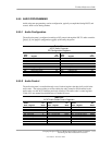
System State Pressed Power Button Results In:
Off Negative pulse, of which the falling edge results in power control logic asserting PS
On signal to Power Supply Assembly, which then initializes. ACPI four-second
counter is not active.
On, ACPI Disabled Negative pulse, of which the falling edge causes power control logic to de-assert the
PS On signal. ACPI four-second counter is not active.
On, ACPI Enabled Pressed and Released Under Four Seconds:
Negative pulse, of which the falling edge causes power control logic to
generate SMI-, set a bit in the SMI source register, set a bit for button status,
and start four-second counter. Software should clear the button status bit
within four seconds and the Suspend state is entered. If the status bit is
not cleared by software in four seconds PS On is de-asserted and the
power supply assembly shuts down (this operation is meant as a guard if
the OS is hung).
Pressed and Held At least Four Seconds Before Release:
If the button is held in for at least four seconds and then released, PS On is
negated, de-activating the power supply.
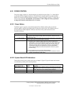
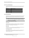
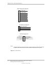
6.2.2.2 System Board LED Indications
Three LEDs located on the system board (refer to chapter 2, figure 2-5) provide status and a means
to troubleshoot possible power-related problems.
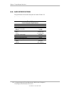
System Board LED
Figure 2-5
Item # Function
Power supply on / 5V aux 19 When illuminated, indicates system is plugged into a live AC outlet
but not
turned on. When off and system is plugged into a live AC
outlet, indicates PS On is asserted (system turned on).
Power button pressed 22 Momentarily illuminates when the power button is pressed.
3.3V aux 25 When illuminated, indicates system is plugged into a live AC outlet.