


Chapter 3 Processor/Memory Subsystem
Compaq Deskpro EXS and Workstation 300 Personal Computers
Featuring the Intel Pentium 4 Processor
First Edition - December 2000
3-8
3.3.3 RDRAM POWER MANAGEMENT
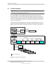
The Rambus architecture provides for power management of each RDRAM device on a RIMM.
RDRAM power management control is compatible with but may also work independently of
ACPI. Power management of RDRAM is handled through control packets as well as the serial bus.
Aside from complete “system off” state, an RDRAM may be placed in one of four basic power
states:
♦ Active
♦ Standby
♦ Nap
♦ Powerdown
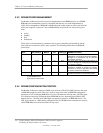
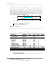
These states are characterized by parameters such as power consumed, refresh method, and the
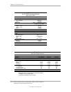
time required to resume full (Active state) operation. The following table defines the RDRAM
power states.
State
Power
Consumed [1]
Refresh
Method
RDRAM
CLK
Exit
Latency [2]
RDRAM Functionality
Powerdown 1 mW Self Stopped
12 µs
Lowest power state and condition entered after
initialization. Can remain in this state indefinitely.
Brought out of Powerdown only by command
over the SIO serial bus.
Nap 10 mW MCH On 90 ns Low power state. Can remain in this state for up
to 10 µs. Brought out of Nap only by command
over the SIO serial bus.
Standby 250 mW MCH On 20 ns Idle power state automatically entered after a
transaction. Available to receive row packets.
Transitions to Active or Nap state upon receipt
of specific command on ROW bus.
Active 500 mW MCH On -- Full power state. Available to receive control
packets and transmit or receive data packets.
NOTES:
[1] Per RDRAM device
[2] Transition to Active state
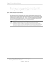
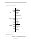
3.3.4 RDRAM CONFIGURATION/CONTROL
The Rambus architecture employs a CMOS-level serial bus (SIO, SCK, CMD) similar to that used
on SDRAM-equipped systems. This bus is used for status and control of RDRAM configuration
parameters as well as bringing RDRAM devices out of Powerdown and Nap states. The SIO signal
is bi-directional and daisy-chained through all RDRAM devices, alternating from SIO0 to SIO1
between devices . The SCK and CMD signals are applied in parallel to all RDRAM devices. The
SCK signal operates at 1 MHz during configuration and at 100 MHz when commands are issued to
switch RDRAM devices from Powerdown or Nap states.