


Chapter 4 System Support
Compaq Deskpro EXS and Workstation 300 Personal Computers
Featuring the Intel Pentium 4 Processor
First Edition - December 2000
4-34
4.7.4 TEMPERATURE SENSING AND COOLING
These systems feature a fan integrated into the power supply assembly. A separate chassis fan is
also employed. Both fans are variable-speed type, and typically operate in tandem as long as the
power supply is active (producing 12 VDC). The fans are off in S3 (Suspend-to-RAM) and S5
(Soft-Off) states.
NOTE: These systems are designed to provide optimum cooling with the cover in place.
Operating a system with the cover removed may result in a thermal condition of system
board components, including the processor.
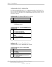
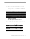
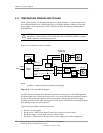
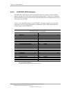
Figure 4-11 shows the fan control schematic.
NOTE:
[1] Will be +12 VDC if chassis fan is connected and operating.
Figure 4-11. Fan Control Block Diagram
An ASIC monitors a thermal diode internal to the processor and provides a Fan CMD signal that
the Speed Control logic of the power supply uses to vary the speed of the fans through the negative
power rail. The turning off of the fans as the result from the system being placed into a Sleep
condition is initiated by the ASIC asserting the Fan Off- signal, which results in the On/Off Control
logic shutting off the +12 volts to the fans.
Typical cooling conditions include the following:
1. Normal – Low fan speed.
2. Hot processor – ASIC directs Speed Control logic to increase speed of fan(s).
3. Hot power supply – Power supply increases speed of fan(s).
4. Sleep state – Fans turned off. Hot processor or power supply will result in starting fans.
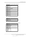
Power Supply Assembly
P1
Speed
Control
Fan CMD
Fan Off-
Fan
Off
PS Fan
CMD
Processor
Sensing
ASIC
On/Off
Control
(+)
(-)
CH Fan CMD
Fan
Sense [1]
SMBus
ICH2
82801
ICH2
Therm-
On/Off
Control
8
12
24
PS Fan
(+)
(-)
2
3
4
Chassis Fan
Header P8
2
3
4
(+)
(-)