


Technical Reference Guide
Compaq Deskpro EXS and Workstation 300 Personal Computers
Featuring the Intel Pentium 4 Processor
First Edition - December 2000
4-17
NOTE: The APIC mode is supported by Windows NT/2000 operating systems. Systems
using the Windows 95 or 98 operating system will need to run in 8259 mode. The mode is
selectable through the Setup utility (access with F10 key during boot sequence).
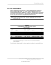
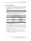
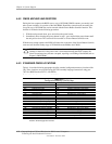
Maskable Interrupt processing is controlled and monitored through standard AT-type I/O-mapped
registers. These registers are listed in Table 4-8.
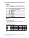
Table 4-8. Maskable Interrupt Control Registers
Table 4-8.
Maskable Interrupt Control Registers
I/O Port Register
020h Base Address, Int. Cntlr. 1
021h Initialization Command Word 2-4, Int. Cntlr. 1
0A0h Base Address, Int. Cntlr. 2
0A1h Initialization Command Word 2-4, Int. Cntlr. 2
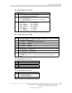
The initialization and operation of the interrupt control registers follows standard AT-type
protocol.
4.4.1.2 Non-Maskable Interrupts
Non-maskable interrupts cannot be masked (inhibited) within the microprocessor itself but may be
maskable by software using logic external to the microprocessor. There are two non-maskable
interrupt signals: the NMI- and the SMI-. These signals have service priority over all maskable
interrupts, with the SMI- having top priority over all interrupts including the NMI-.
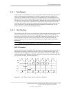
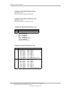
NMI- Generation
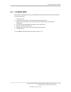
The Non-Maskable Interrupt (NMI-) signal can be generated by one of the following actions:
♦ Parity errors detected on a PCI bus (activating SERR- or PERR-).
♦ Microprocessor internal error (activating IERRA or IERRB)
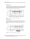
The SERR- and PERR- signals are routed through the ICH component, which in turn activates the
NMI to the microprocessor.