


Chapter 4 System Support
Compaq Deskpro EXS and Workstation 300 Personal Computers
Featuring the Intel Pentium 4 Processor
First Edition - December 2000
4-4
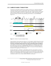
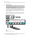
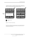
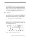
Two types of configuration cycles are used. A Type 0 (zero) cycle is targeted to a device on the
PCI bus on which the cycle is running. A Type 1 cycle is targeted to a device on a downstream PCI
bus as identified by bus number bits <23..16>. With three or more PCI buses, a PCI bridge may
convert a Type 1 to a Type 0 if it’s destined for a device being serviced by that bridge or it may
forward the Type 1 cycle unmodified if it is destined for a device being serviced by a downstream
bridge. Figure 4-2 shows the configuration cycle format and how the loading of 0CF8h results in a
Type 0 configuration cycle on the PCI bus. The Device Number (bits <15..11> determines which
one of the AD31..11 lines is to be asserted high for the IDSEL signal, which acts as a “chip select”
function for the PCI device to be configured. The function number (CF8h, bits <10..8>) is used to
select a particular function within a PCI component.
Figure 4-2. Configuration Cycle
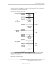
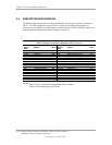
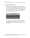
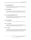
Table 4-1 shows the standard configuration access data for components and slots residing on a PCI
bus.
Table 4-1. PCI Device Configuration Access Data
Table 4-1.
PCI Component Configuration Access Data
PCI Component Vendor/Device ID
PCI
Bus # Device # Function #
IDSEL
Wired to:
82850 MCH:
Memory Controller
PCI/PCI (AGP) Bridge
8086h/2530h
8086h/2532h
0
0
0 (00h)
1 (01h)
0
0
--
AGP slot [3] 1 0 (00h) 0 --
82801BA ICH2:
PCI/PCI Bridge
LPC Bridge
EIDE Controller
USB I/F #1
SMBus Controller
USB I/F #2
AC97 Audio Controller [1]
AC97 Modem Controller [1]
Network Interface Controller [1]
8086h/244Eh
8086h/2440h
8086h/244Bh
8086h/2442h
8086h/2443h
8086h/2444h
8086h/2445h
8086h/2446h
8086h/2449h
0
0
0
0
0
0
0
0
2 [2]
30 (1Eh)
31 (1Fh)
31 (1Fh)
31 (1Fh)
31 (1Fh)
31 (1Fh)
31 (1Fh)
31 (1Fh)
8 (08h)
0
0
1
2
3
4
5
6
0
--
ES1373 Audio Controller 1274h/1373h 2 [2] 31 (1Fh) 0 AD22
PCI Connector 1 (PCI slot 1) [3] 2 [2] 4 (04h) 0 AD20
PCI Connector 2 (PCI slot 2) [3] 2 [2] 9 (09h) 0 AD25
PCI Connector 3 (PCI slot 3) [3] 2 [2] 10 (0Ah) 0 AD26
PCI Connector 3 (PCI slot 4) [3] 2 [2] 11 (0Bh) 0 AD27
PCI Connector 3 (PCI slot 5) [3] 2 [2] 13 (0Dh) 0 AD29
NOTES:
[1] Not implemented on these systems.
[2] Value in standard configuration. Can change if an AGP card with an additional bridge is installed.
[3] Card specific. Refer to appendices.
AD31..0
(w/Type 0
Config. Cycle)
Reserved
Device
Number
Function
Number
Register
Index
Bus
Number
31 24 23 16 15 11 10 8
7 2 1 0 [1]
IDSEL (only one signal line asserted)
Function
Number
Register
Index
Register 0CF8h
Results in:
NOTES:
[1] Bits <1,0> : 00 = Type 0 Cycle, 01 = Type 1 cycle
Type 1 cycle only. Reserved on Type 0 cycle.