


Configurations
1-5
The M-LVDS Evaluation Module
1.4 Configurations
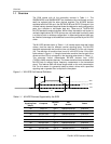
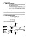
The M-LVDS EVM board allows the user to construct various bus
configurations. The two devices on the EVM allow for point-to-point simplex,
parallel-terminated point-to-point simplex, and two-node multipoint operation.
All of these modes of operation can be configured through onboard jumpers,
external cabling, and different resistor combinations. The devices which are
delivered with the EVM change output operation but, configuration of jumpers
to setup the transmission type is independent of the devices installed
1.4.1 Point-to-Point
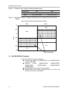
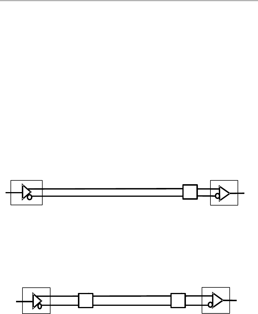
The point-to-point simplex configuration is shown in Figure 1−3. The setup
schematic for this option is shown in Figure 2−1. Although this is not the
intended mode of operation for M-LVDS, it works well for high noise or long
higher-loss transmission lines. Due to the increased drive current, a single
100-Ω termination resistor on the EVM will result in a differential bus voltage
(V
OD
) twice as large as a doubly terminated line. This practice is acceptable
as long as the combination of input voltage and common-mode voltage does
not exceed absolute maximum ratings of the line circuits.
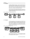
Figure 1−3. Point-to-Point Simplex Circuit
T
U1 U1
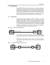
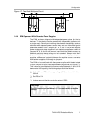
This configuration can also have a termination at the source and load (parallel
terminated), thereby, keeping normal M-LVDS signal levels as shown in Figure
1−4.
The schematic for this option is shown in Figure 2−2. Due to the increased
drive current, double termination can be used to improve transmission line
characteristics .
Figure 1−4. Parallel Termination Simplex Circuit
TT
U1
U1