


Test Results
2-6
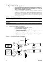
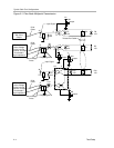
Test Setup
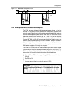
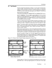
signal on TP1, R2 is shorted. Type-2 behavior is again observed on the
SN65MLVD207 receiver output.
Trace three shows the differential voltage on the bus. Note that the bus volt-
ages are nominal M-LVDS levels of 1.1 V
PP
due to the lower load seen by the
current driver.
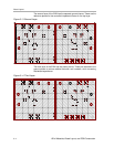
Figure 2−5. Parallel Terminated Point-to-Point Parallel Simplex Typical Eye Pattern Data
Driver
Input
Receiver
Output
Differential
Bus
Voltage
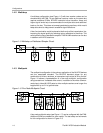
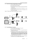
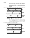
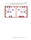
Figure 2−6 represents the two-node multipoint transmission eye patterns
where trace 1 is the input signal applied to J2, and traces 2 and 3 are the output
signals seen at TP1 and TP3 respectively with R2 and R13 shorted. The offset
zero-crossing shows the difference between Type−2 (Receiver #1 Output) and
Type−1 (Receiver #2 Output).
Figure 2−6. Two-Node Multipoint Typical Eye Pattern Data
Driver
Input
Receiver #1
Output
Receiver #2
Output