


PCB Construction
3-7
Bill of Materials, Board Layout, and PCB Construction
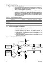
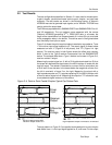
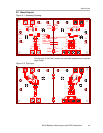
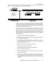
Figure 3−6. Trace Configurations in Printed-Circuit Boards
MICROSTRIP
STRIPLINE
Board
Material
W
h
t
W
t
WS
Stripline construction is the preferred configuration for differential signaling.
This configuration reduces radiated emissions from circuit board traces due
to better control of the lines of flux. The additional ground plane also allows for
better control of impedance on the traces.
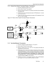
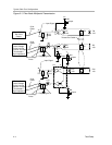
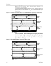
It can be seen from the functions and physical construction parameters that
careful consideration must be given to these parameters for a robust board
design. For instance it is not uncommon for εr to vary 10% across one board,
affecting skew. This is a good reason to keep differential lines close. Other
factors to keep in mind when doing a printed-circuit layout for transmission
lines are as follows:
1) Differences in electrical length translate into skew.
2) Careful attention to dimensions, length and spacing help to insure isola-
tion between differential pairs.
3) Where possible use ideal interconnects, point-to-point with no loads or
branches. This keeps the impedance more uniform from end to end and
reduce reflections on the line.
4) Discontinuities on the line, vias, pads, test points will:
J Reduce characteristic impedance
J Increase the prop delay, and rise-time degradation
J Increase signal transition time
5) Prioritize signals and avoid turns in critical signals. Turns can cause im-
pedance discontinuities.
6) Within a pair of traces, the distance between the traces should be mini-
mized to maintain common-mode rejection of the receivers. Differential
transmission works best when both lines of the pair are kept as identical
as possible.