


Configurations
1-7
The M-LVDS Evaluation Module
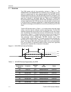
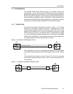
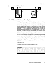
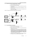
Figure 1−7. Two-Node Multipoint Circuit
T
U1
U2
T
1.4.4 EVM Operation With Separate Power Supplies
The EVM has been designed with independent power planes for the two
devices. The two devices can be powered with independent supplies or with
a single supply. Sending and receiving data between backplanes, racks, or
cabinets where separate power sources may exist can have offset ground
potentials between nodes. Jumpers W7, 8, 9, and 10 tie the two separate
power and ground planes together. If two separate supplies are used and
jumpers W7, 8, 9, and 10 are removed, care should be taken to ensure the
absolute maximum device ratings are not exceeded. Keep in mind that if
jumpers W7, 8, 9, and 10 are not removed when using separate power
supplies, a difference in potential between the supplies causes a current to
flow between supplies and through the jumpers.
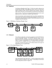
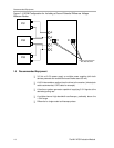
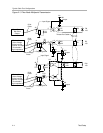
The EVM can be configured with three power supplies with isolated outputs
in such a way as to input a fixed offset between the grounds (see Figure 1−8).
This induces a ground potential difference voltage between U1 and U2. To
demonstrate this capability, the following steps should be followed.
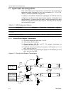
- Adjust PS1 and PS3 to the supply voltage (3.3 V) and current limit to
50 mA.
- Set PS2 to 0 V
- Induce a ground offset by varying the output of PS2.
PS2 Output
The PS2 output should not exceed ± 2 V to remain within the device
ratings.