


Typical Cable Test Configurations
2-2
Test Setup
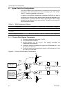
2.1 Typical Cable Test Configurations
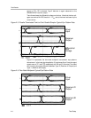
Each of the following test configurations is a transmission line consisting of a
twisted-pair cable connected on the 2-pin connectors (P1, P2, or P3).
Table 2−1 shows the possible configurations.
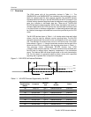
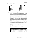
In addition to the different transmission topologies, the EVM can also be
configured to run off two or three separate power supplies, as described in the
previous section. This would allow the user to induce a ground shift or offset
between the two different drivers and receivers. This setup can be used with
any transmission line test.
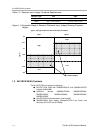
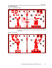
Table 2−1. EVM Configuration Options
Configuration Jumpers In Resistors In Resistors Out Diagram
Point-to-point simplex transmission W1, 2, 7, 8, 9, 10 R4 R5, 6, 7 Figure 2−1
Point-to-point parallel terminated simplex
transmission
W1, 2, 7, 8, 9, 10 R4, 7 R5, 6 Figure 2−2
Two-node multipoint transmission W1, 2, 3, 4, 7, 8, 9, 10 R5, 16 R2, 4, 6, 7, 13 15 Figure 2−3
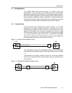
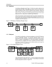
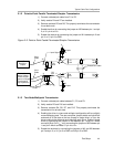
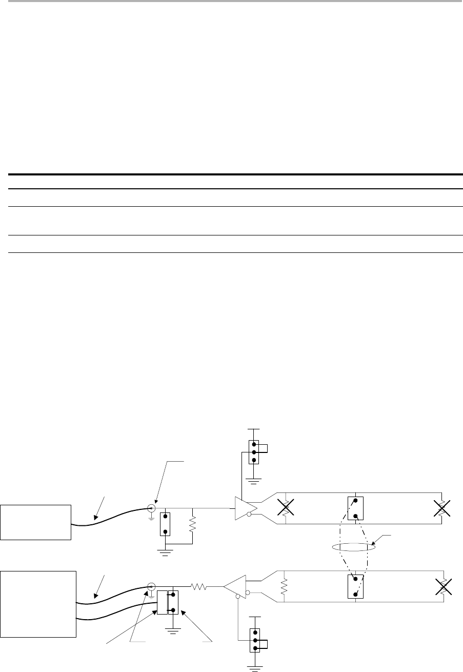
2.1.1 Point-to-Point Simplex Transmission
1) Connect a twisted-pair cable from P1 to P2.
2) Verify resistor R4 is installed.
3) Remove resistors R5, R6, and R7. This properly terminates the
transmission line at one end.
4) Enable the driver by connecting the jumper on W2 between pin 1 and
pin 2, or U1 pin 4 to V
CC
.
5) Enable the receiver by connecting the jumper on W1 between pin 2 and
pin 3, or U1 pin 3 to GND.
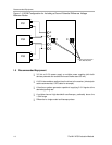
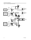
Figure 2−1. Point-to-Point Simplex Transmission
R4
100
R5
100
U1
R7
100
R6
100
U1
11
12
2
9
10
5
P1
P2
Twisted Pair Cable
4
W2
V
CC
Jumper
3
W1
V
CC
Jumper
R3
49.9
J2
Input Signal
R2
453
J1
Output Signal
TP1
TP2
Signal Source
with
Output
50-
Cable
50-
Active Voltage
Probe into one
Channel of Scope
Terminated in
High Impedance
Cable
Active Voltage
Probe
Ω
50-Ω
cable orΩ
50-Ω