


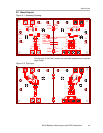


Board Layout
3-4
Bill of Materials, Board Layout, and PCB Construction
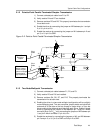
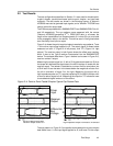
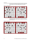
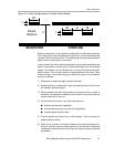
The second layer of the EVM has the separate ground planes. These are the
reference planes for the controlled impedance traces on the top layer.
Figure 3−3. Second Layer
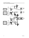
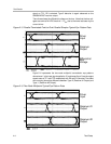
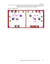
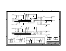
The third layer of the EVM has the power planes. These are matched to the
ground planes to reduce radiated emission and crosstalk, while increasing
distributed capacitance.
Figure 3−4. Third Layer