


Configurations
1-6
The M-LVDS Evaluation Module
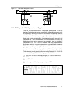
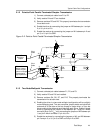
1.4.2 Multidrop
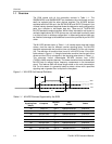
A multidrop configuration (see Figure 1−5) with two receiver nodes can be
simulated with the EVM. To get additional receiver nodes on the same bus
requires additional EVMs. M-LVDS controlled driver transition times and
higher signal levels help to accommodate the multiple stubs and additional
loads on the bus. This does not exempt good design practices, which would
keep stubs short to help prevent excessive signal reflections.
A bus line termination could be placed at both ends of the transmission line,
improving the signal quality by reducing return reflections to the driver. This
would allow the use of standard compliant TIA/EIA 644A receivers on the bus
in addition to M-LVDS receivers.
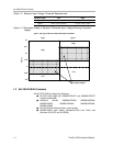
Figure 1−5. Multidrop or Distributed Simplex Circuit
T
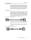
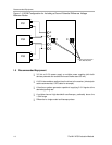
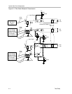
1.4.3 Multipoint
The multipoint configuration is the primary application of the M-LVDS devices
and the associated standard. The M-LVDS standard allows for any
combination of drivers, receivers, or transceivers up to a total of 32 on the line.
Figure 1−6 shows a representation of a five-node multipoint configuration
using transceivers. Increased drive current, in addition to the wider common-
mode input, allows M-LVDS parts to drive multiple receivers over longer line
lengths with up to 2 V of ground noise.
Figure 1−6. Five-Node Multipoint Circuit
T
T
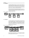
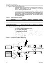
A two-node multipoint setup (see Figure 1−7) can be configured with the EVM.
Additional EVMs are needed for more nodes. The test setup and schematic
for this configuration is shown in Figure 2−3.