


Test Results
2-5
Test Setup
2.2 Test Results
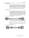
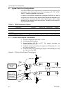
The test configurations described in Section 2.1 were used to simulate point-
to-point simplex, parallel-terminated point-to-point simplex, and two-node
multipoint. The test results are shown in the following figures. A Tektronix
HFS9003 was used to generate input signals, and a Tektronix TDS784D was
used to collect the output data.
The EVM was populated with a SN65MLVD207D and SN65MLVD201D for U1
and U2 respectively. The eye patterns were measured with the source
(Tektronix HFS9003) generating 2
15
−1 PRBS NRZ data. In all cases, the
length of the transmission line is approximately 21 inches (53 cm), and adds
to the propagation delay in the device. This can be seen in the figures below
as a time delay from input to output
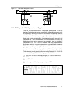
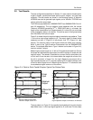
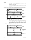
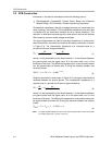
Figure 2−4 shows the point-to-point simplex transmission eye patterns. Trace
1 is the driver input signal applied to J2. The output signal is shown below
measured on both J1 (Figure 2−4 left picture), and TP1 (Figure 2−4 right
picture). The receiver output in both figures shows the offset zero crossing,
which is due to the Type-2 receiver incorporated into the SN65MLVD207
device. The reduced offset from a Type-1 receiver can be seen in Figure 2−6,
receiver number 2 output.
Measuring the output signal on J1 with a 50-Ω cable terminated into 50-Ω at
the scope will attenuate the signal due to the 453-Ω resistor in series with the
receiver output. The resistor is installed as a current limit for termination into
a 50-Ω load. As can be seen in the traces below the magnitude of trace 2 on
the left is one-tenth of trace 2 on the right. Measuring the signal with a
high-impedance probe on TP1 requires replacing R2, the 453-Ω resistor, with
a short to reduce signal roll-off. Measuring the output on TP1 allows the user
to see absolute signal levels out of the device.
Figure 2−4. Point-to-Point Parallel Simplex Typical Eye Pattern Data
Receiver Output Scaled 10:1
50-Ohm Output Termination
High Impedance Output Termination, R2 Shorted
Driver
Input
Receiver
Output
Differential
Bus
Voltage
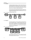
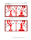
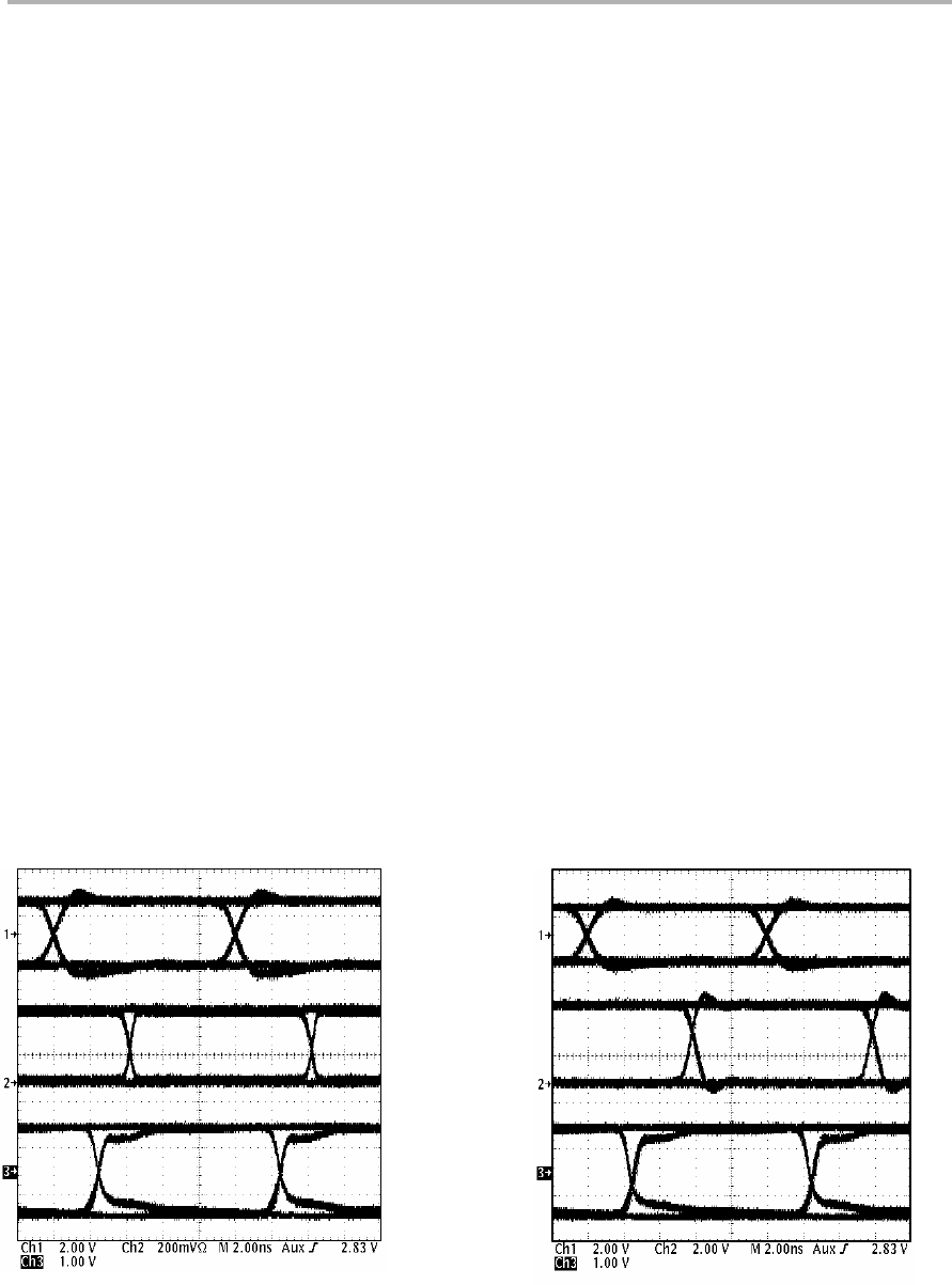
The eye patterns in Figure 2−5 are parallel-terminated point-to-point simplex
data where trace 1 is the input signal applied to J2, and trace 2 is the output