


PCB Construction
3-6
Bill of Materials, Board Layout, and PCB Construction
3.3 PCB Construction
Information in this section was obtained from the following source:
- Electromagnetic Compatibility Printed Circuit Board and Electronic
Module Design, VEC workshop, Violette Engineering Corporation.
Characteristic impedance is the ratio of voltage to current in a transmission line
wave traveling in one direction. This characteristic impedance is the value that
is matched with our termination resistors so as to reduce reflections. This
reduction in reflections improves signal to noise ratio on the line and reduces
EMI caused by common mode voltages and spikes.
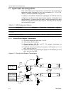
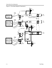
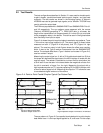
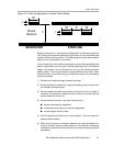
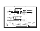
Two typical approaches are used for controlled impedance in printed-circuit
board construction, microstrip and stripline. Microstrip construction is shown
in Figure 3−6. The characteristic impedance of a microstrip trace on a
printed-circuit board is approximated by:
Z
O
+
60
0.475år ) 0.67
Ǹ
ln
4h
0.67
(
0.8 W ) t)
(1)
where εr is the permeability of the board material, h is the distance between
the ground plane and the signal trace, W is the trace width, and t is the
thickness of the trace. The differential impedance for a two microstrip traces
can be approximated as follows with S being the distance between two
microstrip traces:
Z
DIFF
+ 2 Z
O
ǒ
1 * 0.48e
*0.96sńh
Ǔ
(2)
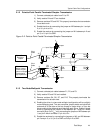
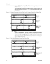
Stripline construction is also shown in Figure 3−6, the signal lines should be
centered between the ground planes. The characteristic impedance of a
stripline trace in a printed-circuit board is approximated by:
Z
O
+
60
år
Ǹ
ln
4h
0.67p
(
0.8 W ) t)
(3)
where εr is the permeability of the board material, h is the distance between
the ground plane and the signal trace, W is the trace width, and t is the
thickness of the trace. The differential impedance for a two stripline traces can
be approximated as follows with S being the distance between two stripline
traces:
Z
DIFF
+ 2 Z
O
ǒ
1 * 0.374e
*2.9sńh
Ǔ
(4)
Note: For edge-coupled striplines, the term 0.374 may be replaced with 0.748 for lines which
are closely coupled (S < 12 mils, or 0,3 mm).