


CY7C1246V18, CY7C1257V18
CY7C1248V18, CY7C1250V18
Document Number: 001-06348 Rev. *D Page 14 of 27
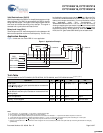
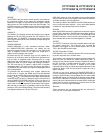
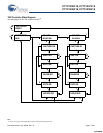
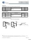
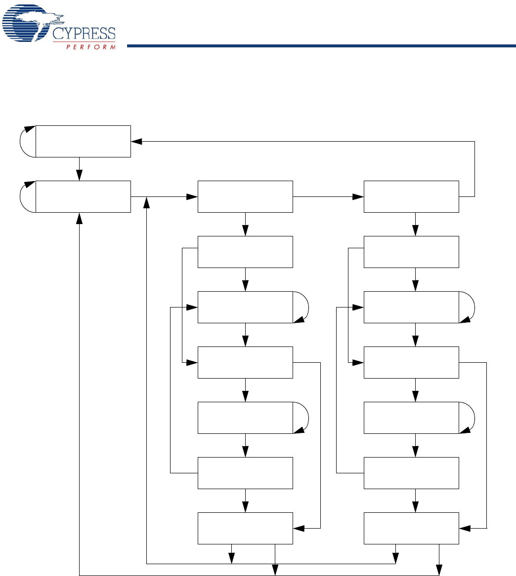
TAP Controller State Diagram
The state diagram for the TAP controller follows.
[9]
TEST-LOGIC
RESET
TEST-LOGIC/
IDLE
SELECT
DR-SCAN
CAPTURE-DR
SHIFT-DR
EXIT1-DR
PAUSE-DR
EXIT2-DR
UPDATE-DR
SELECT
IR-SCAN
CAPTURE-IR
SHIFT-IR
EXIT1-IR
PAUSE-IR
EXIT2-IR
UPDATE-IR
1
0
1
1
0
1
0
1
0
0
0
1
1
1
0
1
0
1
0
0
0
1
0
1
1
0
1
0
0
1
1
0
Note
9. The 0/1 next to each state represents the value at TMS at the rising edge of TCK.
[+] Feedback [+] Feedback